Blog Posts

#19 Gantry Assembly / Finalizing Sensor Design

Team Locker Filled With Recent POs

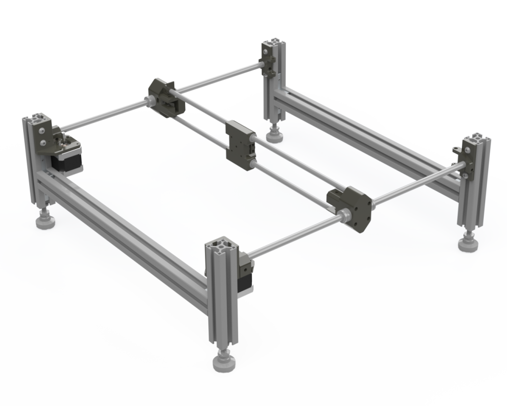
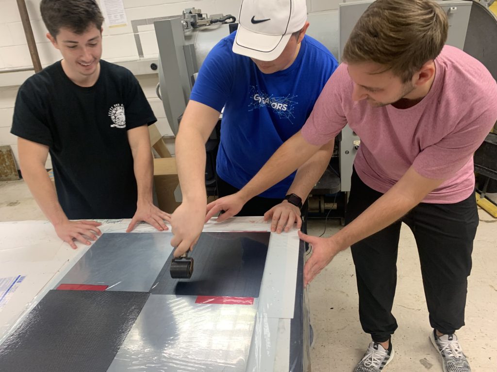
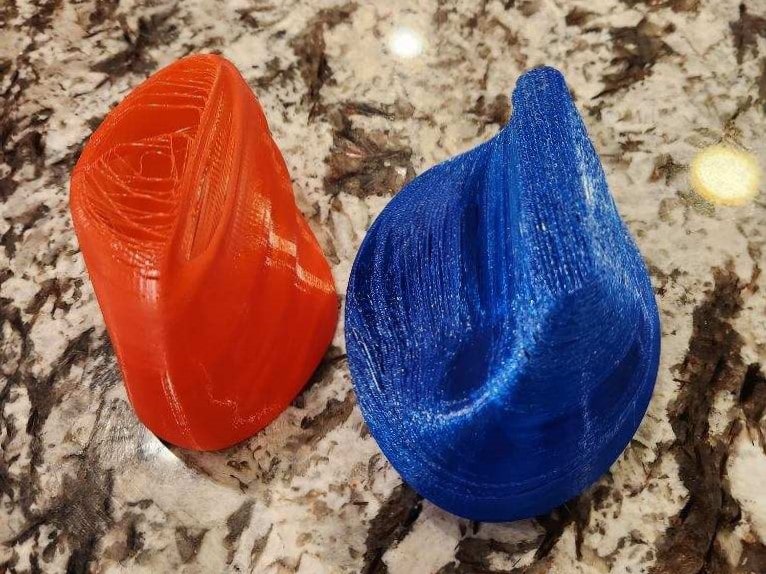
As we move into the testing phrase of the spring semester, we have most of the gantry components in and assembly has begun. Our team is working diligently to put everything together and make sure that everything fits as it should. In addition, we have been 3D printing gantry structural components and this has been going smoothly.

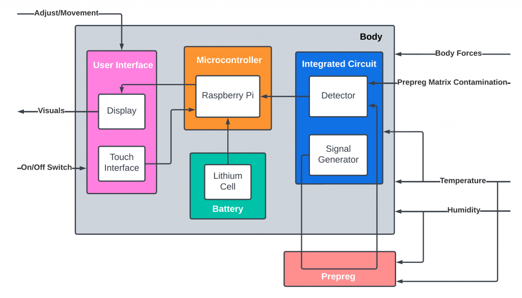
We are in our final stages of the sensor PCB design. The PCB design will be sent over to a PCB expert for review before we place the order. This is a critical component of our project and we are confident that it will function as intended.

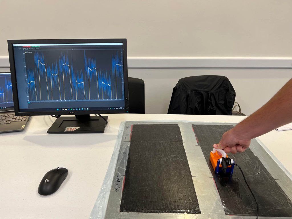
The sensor device has also been verified to have the capability to be battery powered. This is an important milestone for us as it means that our device can be used in a wide range of settings without the need for an external power source.

Moving forward, our plans for the next week include finalizing and making the PCB order, considering modifications to be made for the transition from a gantry to a handheld device, and testing the gantry and stepper system function. We will continue to keep you updated on our progress. See you next week!

#18 QRB 1 Week

Title Presentation Slide from QRB1

We recently presented at the Quarterly Review Board 1 (QRB1) and received positive feedback on our progress. We are now moving forward with submitting gantry and electronics purchase orders, which will transition us into the testing phase of the spring semester

One of the key aspects of our project is the capacitive sensor, and we are looking for an electrical engineering professor or student who is skilled in PCB design to review our designs. This will not only help us ensure the functionality of our sensor but also provide valuable feedback for improvement.

We are confident that this expert review will help us deliver a high-quality final product that meets our objectives. We will keep you updated on our progress and look forward to sharing the final results with you.

Tagged as: , ,

#17 Preparation for QRB1

This week, we made great strides toward preparing ourselves for QRB 1. We created a testing timeline to ensure that we stay on track and meet our deadlines. We also made a preliminary design of our eddy current sensor, which will be used along side the capacitive sensor. After some insight from our liaison, we decided to stick with a handheld device instead of a gantry system for the final product, as it would be more practical on the shop floor. The gantry system will purely be used for testing the handheld devices, since any change in holding pressure on the device will result in extra noise in the data.

Gantry Design Render (Test Bench)

Moving forward, we are planning to consider ways to account for human error in the testing environment. This will ensure that our results simulate what will happen if the device was introduced in the field with manufacturing operators. We will also be completing purchase orders for any necessary materials and equipment. Additionally, we will be looking into incorporating springs into the design of the sensor array, to ensure even surface contact. Finally, after we gather more indicative data, we will begin development of the inclusion detection firmware.

#16 Compiling Order List

The team is currently in the midst of a pure work week on the project. The team has been divided into two groups where Kolten and Tyler are working on the gantry design and assembly while Peyton and Erin are working on the capacitive and eddy current sensor design. We are focused on compiling a bill of materials for the following systems:

  • gantry test bench (electronics, frames, fasteners)
  • capacitive sensor (custom PCBs, electrical components)
  • eddy current (OEM PCB, electrical components)

Our goal is to place a mass purchase order for all the necessary parts in order to move forward with the project efficiently. Stay tuned for updates on our progress.

Spring Semester Plan

#15 Spring Semester Kickoff

Welcome back to the spring semester, readers! We are are excited to tackle the final stage of our project. This stage consist of the following:

  • final testing of sensors
  • manufacturing of the sensor housing, device casing, and gantry testing bench
  • developing bind testing samples
  • creating poster design and demonstration video
  • presentation of our final product to the sponsor company, Northrop Grumman

We are eager to embrace the challenges that lie ahead and make the most of this opportunity. Our team has already setup a “whentomeet”, so we can get everyone’s schedules. This way, we can coordinate coach and liaison meetings for the spring semester immediately.

We are going to roll up our sleeves and get to work. We can’t wait to see what we’ll achieve as a team!

#14 SLDR Week

Early this week, we presented our System Level Design Review (SLDR) presentation to classmates, coaches, and IPPD liaisons. Before the presentation, we had the pleasure of having Jamie J. Kraft, UF Director of the Entrepreneurship Program, give the opening speech for the SLDR event. The event provided us with helpful feedback to improve our presentation delivery as well as got us into the mindset of an entrepreneur.

Team Photo with Mary Alice after SLDR Presentation

We were ecstatic to have Mary Alice present during our SLDR presentation. The final revision of the SLDR report has been completed and sent to our liaison engineers. We cannot wait to show Mary Alice and Jessica, liaison engineers from Northrop Grumman, our progress at our next project milestone during the spring semester. This will be the final blog post for the fall semester. We would like to thank everyone that has tuned into our weekly posting, and we want to wish everyone an amazing winter break.

#13 Preparing for SLDR

We, Composite Guardian, hope everyone had an amazing Thanksgiving Break. We did perform some last data collection from our capacitive sensor prototype before we left for break. The peaks and dips in the data proved that transitions between the defect areas to non-defect areas could be seen.

Fall Data Collection on Uni-directional prepreg

Right after we came back from Thanksgiving Break, we came together as a group to finish the last few sections of the draft System Level Design Review (SLDR) report and presentation slides. During the peer review presentation for the SLDR, we received meaningful feedback from our peers on how to improve the flow of the presentation and explanation of the data.

In order to limit the amount of noise from the data, we decided to prepare a more professional set of testing samples. This time with the testing samples, each step of the layup process was executed with precision. Our main goal for the new testing samples was to eliminate the number of wrinkles and air bubbles within our prepreg layers so we could focus on finding backer material within prepreg layers exclusively. After completing the testing sample, we quickly conducted a speed test, as shown in the video below.

Making Process of Testing Sample V3

For the last 2 weeks of the semester, we will be preparing for our SLDR presentation and putting our final touches on the SLDR report. We plan on continuing the development of firmware to prepare for full system integration, finalize the second design iteration, integrate a speed testing measure on TPM, and create a model eddy current circuit early next semester.

Speed Test on Testing Sample V3

#11 Prototype Inspection Week

Group photo after PID

Prototype inspection day (PID) was a success. We received valuable feedback from a variety of judges with expertise ranging in electrical engineering, mechanical engineering, and material science. For PID, we completed a simple board design to test capacitive sensing and enclosed it within a 3D-printed body. We also prepared a trifold design with all the necessary information for judges to understand our problem and see what we are planning to do to solve the problem.

During our presentation, we demonstrated a live demo of the backer detector represented in the image on the right. The monitor is showing the real-time capacitance measurements from the device. We were alternating between a defect area to a non-defect area which is represented in the two different peaks alternating on the monitor. The detector senses in the pF range with fF differences.

Demonstration of the detector during PID

We have developed a plan to improve the shielding of the sensor since the sensor is super sensitive. Any inputs to the system like touching the metal plate to the pressure applied on the device handle can significantly increase noise in the capacitance readings. In the upcoming weeks, we plan on testing some shielded sensors options and looking into multiple sensor array or heterogenous testing (potentially eddy current) to have higher result resolution.

#10 Preparing for PID

With us only having a 3-day school week, we have successfully developed & 3D-printed 3 different detector body designs, created a new testing station with samples varying in inclusion sizes and layer depth, and organized the presentation setup for prototype inspection day.

With the 3D-printed bodies, we wanted to get feedback from the judges during PID on the ergonomics of each detector casing design. Each judge will get the opportunity to handle each design and then rank them from first to last on comfort.

Poster Board Layout
3D Prints of 2 designs (3rd design is printing at the time of blog post)
Top (Uni-directional) and Bottom (Woven)

There were two reasons why we had to make new testing samples. The first reason, we used our coach’s lab equipment to lay up our first samples, and then the equipment was needed by his graduate students. Second, we wanted to diversify our testing samples to include more variations of inclusions within layers. Each layup in the image on the left has 3 sections, we have the left section (4 layers – defect in different layers), the middle (2 layers – 1 in^2 defect), and the right (2 layers – large defect).

Next week, we plan on exploring options for shielding with a capacitive sensor, investigating more into eddy current detection, completing board design for PID, updating device code, and creating curved surface and multidirectional orientation samples for future testing.

#9 Prototype Testing

Prototype Inspection Day (PID) is approaching quickly, but we are not far from our final prototype design since we have been making major improvements to our capacitance sensor circuit and device functionality. As we get closer to the final design, the blog will, unfortunately, consist less of the circuit design since we still have to follow the NDA standards set by IPPD and Northrop Grumman.

This week, we presented our prototype architecture in front of the entire class. We received amazing feedback from classmates and plan to incorporate all suggestions to improve our architecture in the next report.

During our coach meeting this week, we were happy to have Dr. Mark Orazem in the meeting to clarify the possibility of electrical impedance as a detection method. After the discussion we had with Dr. Mark Orazem, we plan to continue developing our capacitance-sensing device because of potential issues with electrical impedance on semi-solid surfaces (in our case prepreg).

Next week, we plan on developing representative samples of curved composites with defects, 3D printing a couple of prototype casings, continuing to test the prototype’s detection reliability, and creating a poster board presentation for PID.