With us only having a 3-day school week, we have successfully developed & 3D-printed 3 different detector body designs, created a new testing station with samples varying in inclusion sizes and layer depth, and organized the presentation setup for prototype inspection day.
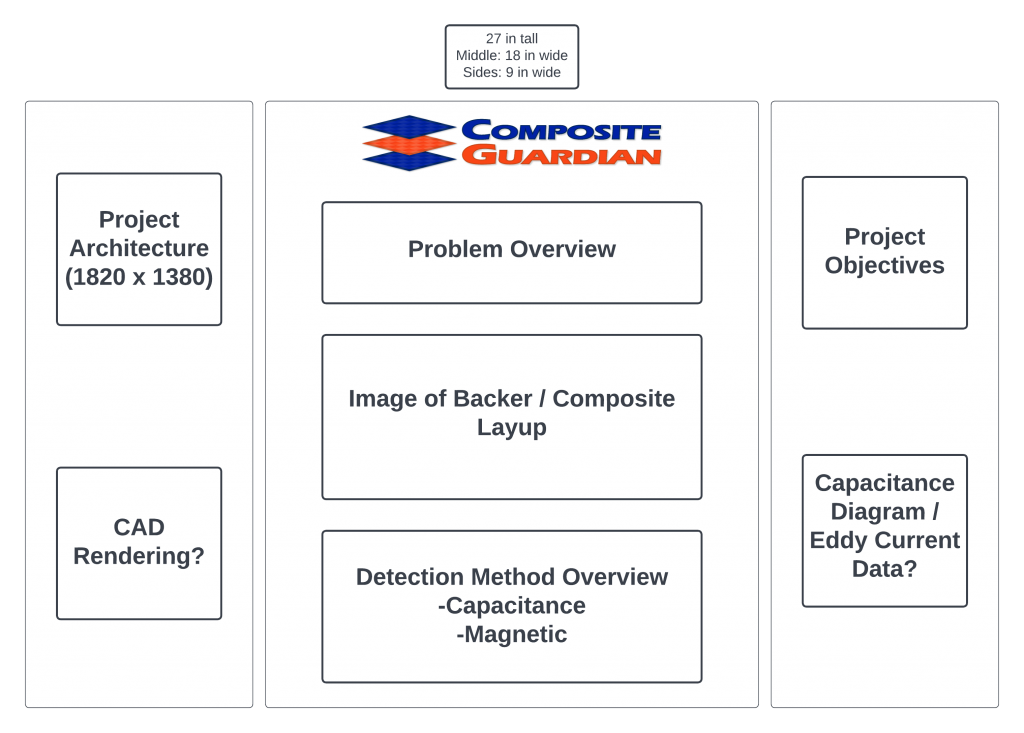
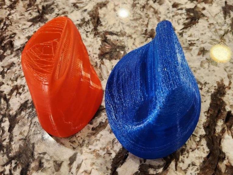
With the 3D-printed bodies, we wanted to get feedback from the judges during PID on the ergonomics of each detector casing design. Each judge will get the opportunity to handle each design and then rank them from first to last on comfort.
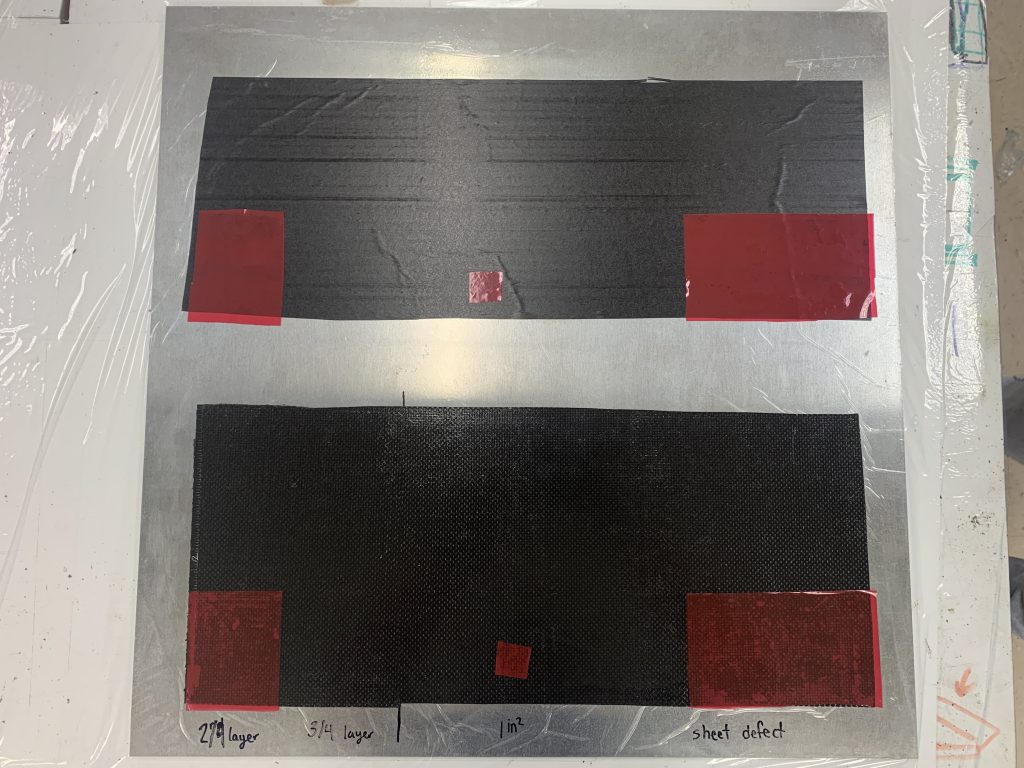
There were two reasons why we had to make new testing samples. The first reason, we used our coach’s lab equipment to lay up our first samples, and then the equipment was needed by his graduate students. Second, we wanted to diversify our testing samples to include more variations of inclusions within layers. Each layup in the image on the left has 3 sections, we have the left section (4 layers – defect in different layers), the middle (2 layers – 1 in^2 defect), and the right (2 layers – large defect).
Next week, we plan on exploring options for shielding with a capacitive sensor, investigating more into eddy current detection, completing board design for PID, updating device code, and creating curved surface and multidirectional orientation samples for future testing.