As we come to the end of IPPD, we can confidently say that it has been an amazing experience. We worked in interdisciplinary team, faced challenges, and received invaluable feedback during design reviews. Through it all, we grew as individuals and as a team, and we are proud of what we have accomplished. Thank you to our coach, liaisons, and classmates for making this journey unforgettable. We can’t wait to see what the future holds for our project and for all of us.
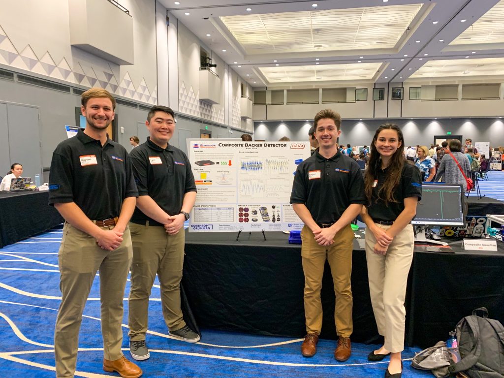
We are excited to share our final update on our IPPD project, where we developed a sensor-based system for backer defect detection in composite structures. Our project has reached its final stages, and we are proud of the progress we have made over the two semesters.
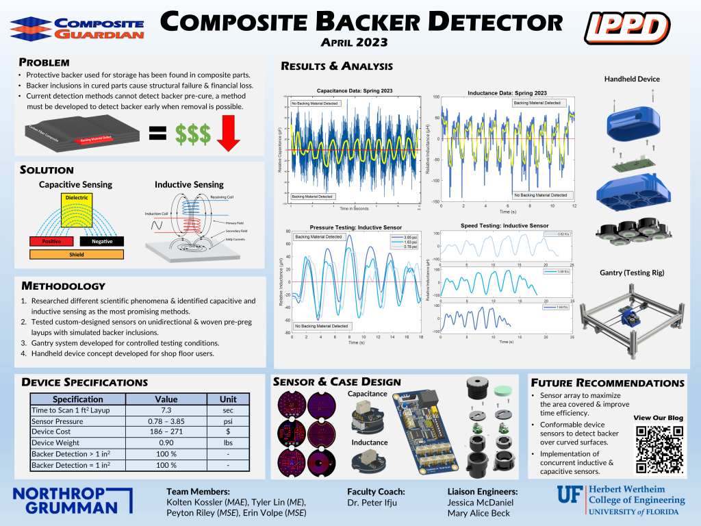
Final Poster Design
One of our significant accomplishments is collecting data for variable speed, pressure, and inclusion size for inductive sensors. We found that the capacitive sensor is very noisy during movement and must be placed or moved slowly to get readable values. This knowledge will help us in developing a robust and reliable sensing system.
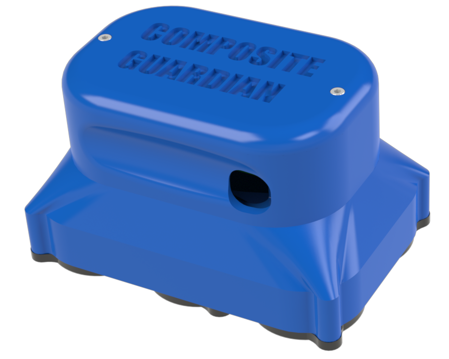
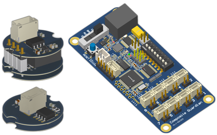
Handheld Device Render
We also created a 3D model for our handheld device, which will be used for testing and further development. Moving forward, we plan to complete the 3D handheld model print for a sample run to put into a video and FDR presentation. We received valuable feedback on our FDR presentation and incorporated changes to improve the event’s overall presentation. Additionally, we completed future recommendations and a user manual to support future work on this project.
We would like to express our sincere gratitude to our liaisons for their invaluable support throughout the project. Their guidance and expertise have been instrumental in our success. In conclusion, we are proud of the progress we have made and are excited to share our final product with everyone.
Welcome back to our blog! With the peer FDR presentation next week, we are doing our final sensor testing data before manufacturing our final product. The test consists of scanning speed, sensor pressure, larger than 1-inch square detection, and less than 1-inch square detection. These are significant steps towards achieving real-time monitoring of composite structures, which is crucial for early detection of material defects. During the in-class review of our video draft, we received many compliments on our video production quality. We also got amazing feedback on how to make our problem in the video more noticeable. There is still more work to be done on the video which include filming the handheld device being used.
Sensor Pressure Testing Rig
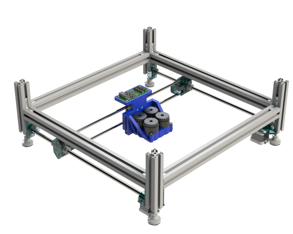
Final Gantry Render
Furthermore, we applied an exponential moving average to the data obtained from the sensors to determine the viability of using a threshold indication for detecting material defects. The results were promising, and we plan to evaluate this method further on thicker samples. Our next steps will include compiling the data summary into reports for discussion on sensing viability, optimizing the threshold indication based on scanning time, and analyzing different sensor uses for the future work section of our final report.
We are excited about the progress we have made and look forward to sharing more updates with you as our project continues to develop. Thank you for your interest in our work.
We were able to add hardware to minimize noise on the capacitive sensor, which will help us get more accurate data. Additionally, we were able to fix hardware issues with the MCU and are now about to test communication.
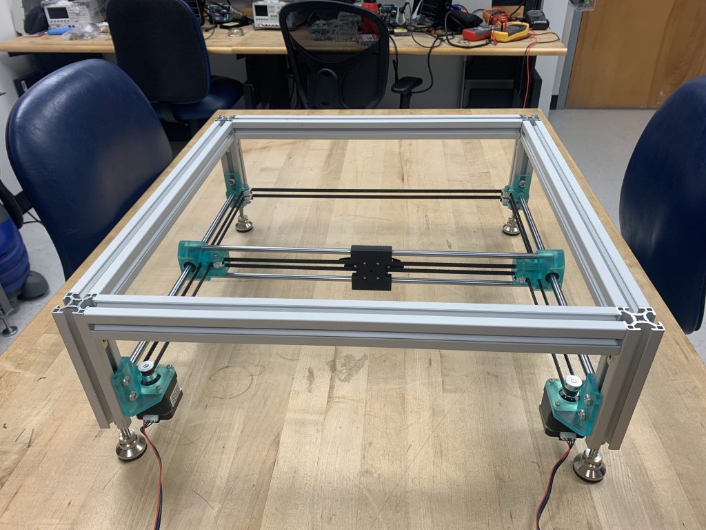
We also finalized the gantry sensing pattern, which will allow us to collect data more efficiently. Regarding media, we began collecting clips and stock b-roll footage for the project overview video. To prepare for the future work section of the project, we identified important ideas to comment on, such as a handheld device and array.
Intro to Promo Video
Additionally, we completed inductive code communication, but still need to work on troubleshooting and optimization. Looking forward, our plans for the next week include collecting capacitive and inductive data, validating inductive sensor code and function on a test surface, creating 3D models for the future work section, and completing a user manual for the basics of the device.
The team has been hard at work after prototype inspection day 2. In terms of accomplishments, we have obtained initial capacitance test data with higher resolution than last semester, thanks to the new electronics and gantry. We have also found the optimum pressure for the capacitance sensor with the screw top in the casing; however, we still need to quantify this value. In addition, we have completed the preliminary inductive sensor code.
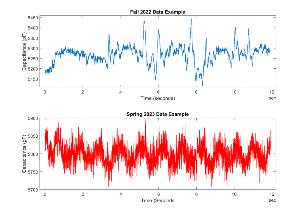
Fall vs. Spring Data Comparison (oscillating between defect and non-defect areas)
After collecting the spring data by manually moving the device on the gantry, we were able to solve the issue with the stepper motor for the gantry. With the issue fixed, the gantry was able to automatically translate around the scanning area.
Moving forward, we have several plans for the upcoming week. We aim to quantify the pressure and speed values for sensing and add filtering hardware and firmware for clearer signals. We will also troubleshoot the inductive sensor function and gather data to refine our results. Lastly, we will continue working on the 3D models for the final prototype casing, which will be a handheld device.
Greetings readers! We have some exciting updates to share with you regarding our ongoing project.
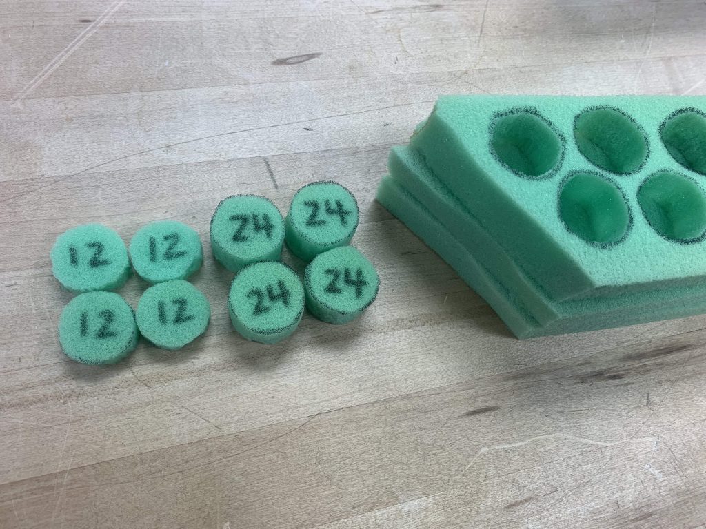
Firstly, we’ve corrected some soldering issues with our PCBs and continued working with our sensor code and device integration. We’ve also completed the design for the sensor housing and have successfully printed the sensor casing to attach to the gantry. In addition, we’ve cut foam cylinders to act like springs within our sensor casing to provide constant pressure onto the sensor during use.
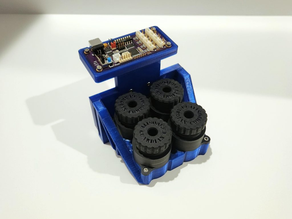
3D Printed Sensor Housing With Mainboard & Sensors Installed
2 Sets of Cylinder Shaped Foam for Sensor Casing
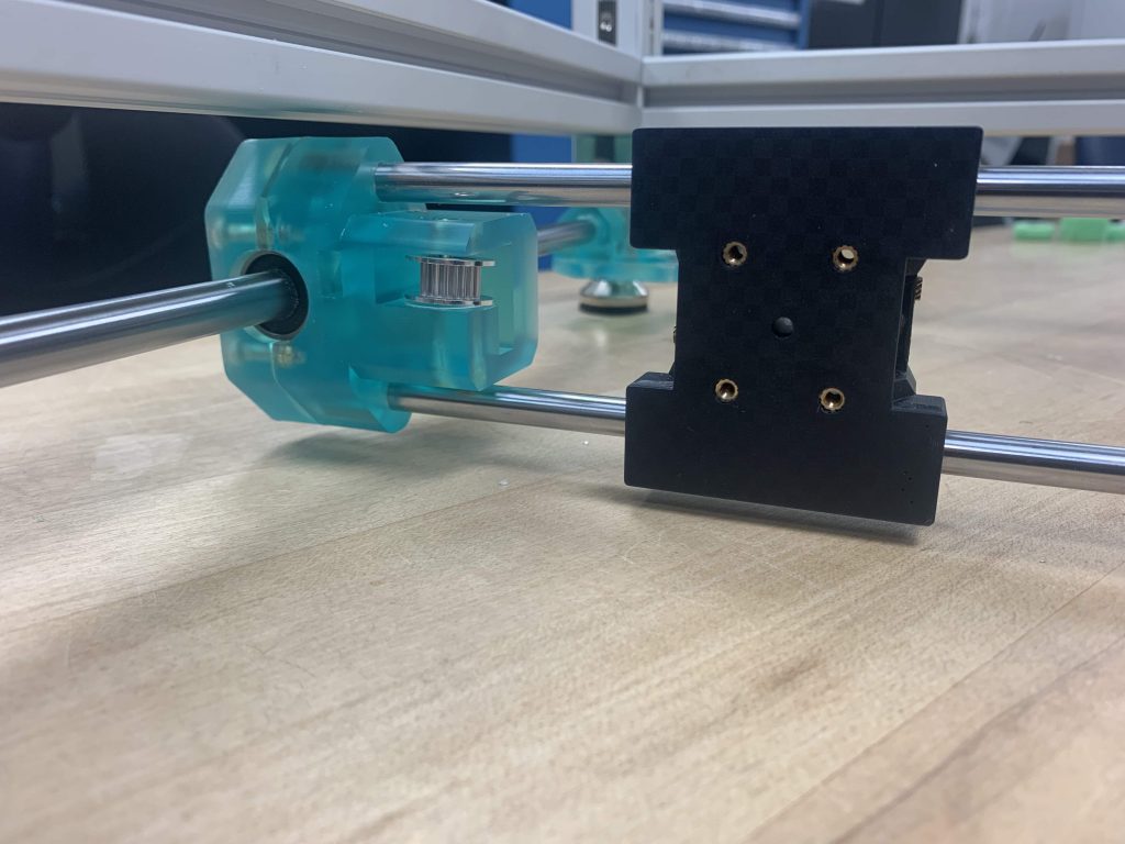
In preparation for our upcoming prototype inspection day, we’ve made some modifications to the gantry. Specifically, we’ve enabled manual movement of the attached sensor housing as electronic issues were causing excessive vibrations. This modification not only resolves the issue of excessive vibrations, but also allowed the sensor housing to be closer to the scanning surface. This will require less 3D printing material for the sensor housing to be close to the prepreg surface.
Assembled Gantry V3
Closeup of Sensor Casing Attachment Location
As for our plans for the upcoming week, we aim to remake test samples and run them with individual sensors for cleaner electronic data. We will also continue to test and troubleshoot our inductive sensor code with the device either this weekend or early next week. Furthermore, we plan to continue work on our motherboard code and begin testing with the PCB. Finally, we will be verifying the iolab cart speed with the gantry movement.
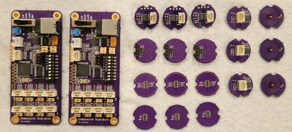
This week has been filled with assembly and testing tasks. On the sensor side, we have fully assembled both the inductive and capacitive sensors, as well as the motherboard and spares. We’re happy to report that everything came together smoothly. We tested the capacitive sensor by plugging it into an Arduino, and the results were promising. We achieved four times the sampling accuracy than the previous prototype, which is a significant improvement. It was a good indication that we were on the right track.
Assembled Gantry V2
On the gantry side (testing rig), we have replaced some faulty gantry parts to improve its functionality, and we calibrated the gantry code for preliminary trials. With the sensor housing device, we determined that using foam instead of a spring to apply equal surface pressure on the sensor housing would be more effective.
In the next week, we should be receiving the ordered missing motherboard part (can still run preliminary trials without it). We plan to print the sensor casing for gantry attachment and cut foam to fit within the sensor casing. We’ll also finalize the gantry code structure for speed testing and gather preliminary results for use speed indications. We’ll complete a preliminary code for the motherboard design and perform individual tests of the inductive sensor function through the Arduino plug-in.
Please note that we won’t be posting a blog next week because of spring break, but we’ll resume our regular updates afterward.
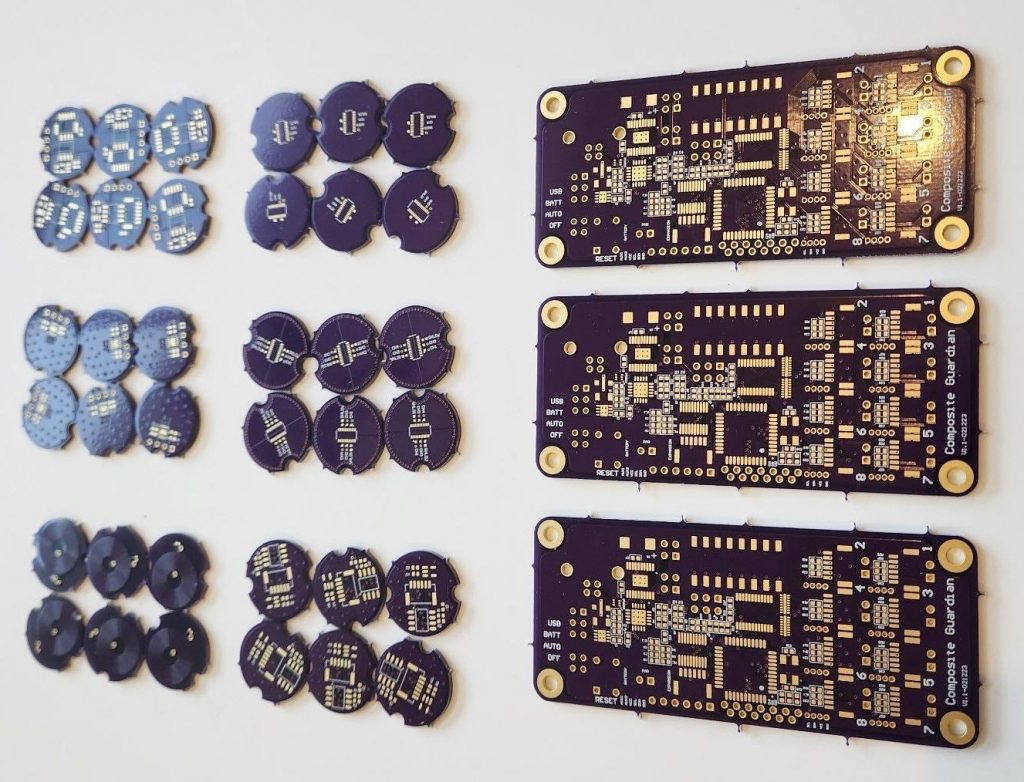
We recently completed QRB2 with positive reviews and valuable feedback around our testing plans. It was an excellent opportunity for us to present our project and receive feedback from fellow IPPD coaches. Just recently, we acquired our blank PCB designs and can finally start assembling all the electronic components onto the PCBs.
We’ve also made significant progress on the mainboard construction for the sensing system. We’ve updated the pseudocode for the sensors from the previous prototype to the new one, improving the sensing system’s precision and accuracy. We’ve also updated the user manual outline to match typical device manuals, ensuring that users will be able to use our product easily.
Recently received bare PCB boards
We’ve attached the gantry belt and completed all parts’ construction, except for the sensor housing. Our team has finalized the stepper motor code structure, which utilizes a universal g-code sender. We’re pleased with the results and confident that it will perform well in our testing.
Our team has been working diligently on completing the PCB construction, finishing the sensor code for value reading, printing the sensor casing for the gantry, and checking the stepper motor speed with the cart test setup for human use measurements.
It’s been another busy week for our team, and we’re thrilled to share our latest updates with you. We have incorporated the 3D printed parts onto the gantry, and this allowed us to attach the stepper motors and linear rods as well. The components to complete the gantry assembly are the sensor carriage print and belt incorporation. A heat insert defect did prevent us from installing the stepper belts.
On the topic of sensors, we’ve also made progress on the model for the sensor housing on the gantry. It’s great to see it come to life, and it’s really helpful for visualizing how the sensor will fit on the gantry. In addition, we’ve outlined the user manual, it’s essential to have a clear and concise guide for users to operate our device effectively.
Looking forward, our plans for the next week include constructing sensing devices by printing carriage and incorporating PCBs, completing pseudocode for the sensing system, testing PCB function once parts come in, and making sure that the speed of the stepper motor matches the cart for human error testing. It’s a lot to do, but we’re ready to tackle it head-on.
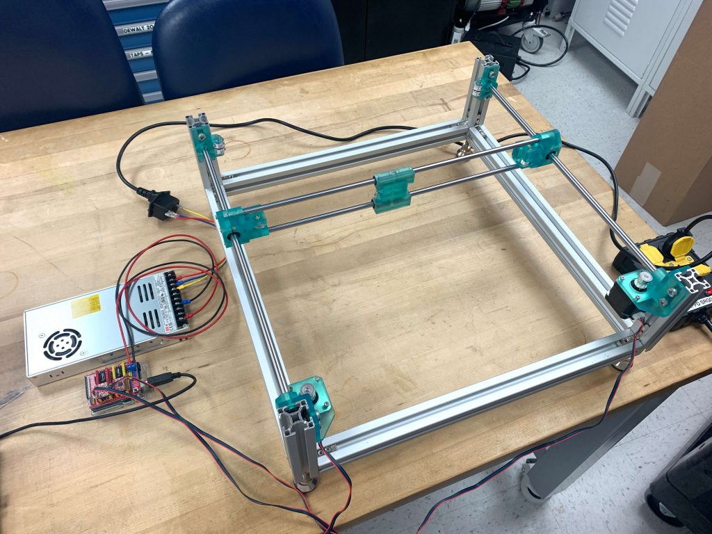
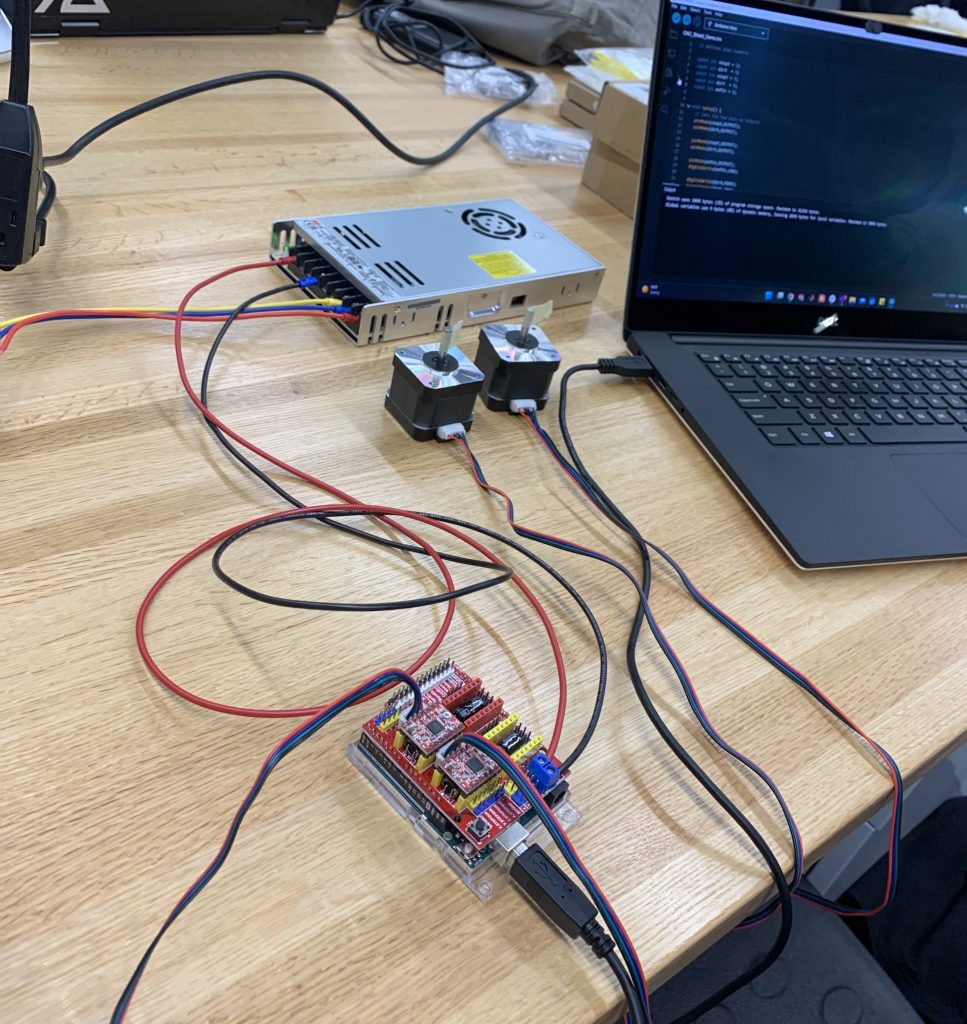
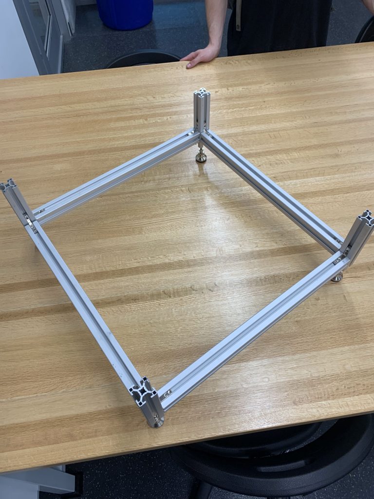
With the QRB 2 coming soon, we wanted to ensure that everything is functional from the components we purchased. We have assembled the basic gantry structure and ensured stepper functionalities. We have also designed human error testing and ordered parts to investigate variations in speed and pressure of a handheld device. This will help us to better understand the variability of our device and make any necessary modifications to ensure its accuracy. In addition, we had an hardware engineer review our PCB designs. After validation from the expert, we placed the sensor PCB purchase orders (POs). With the expert’s feedback, we are confident that our sensor PCBs will function as intended.
Validating Functionality of Gantry Electronics
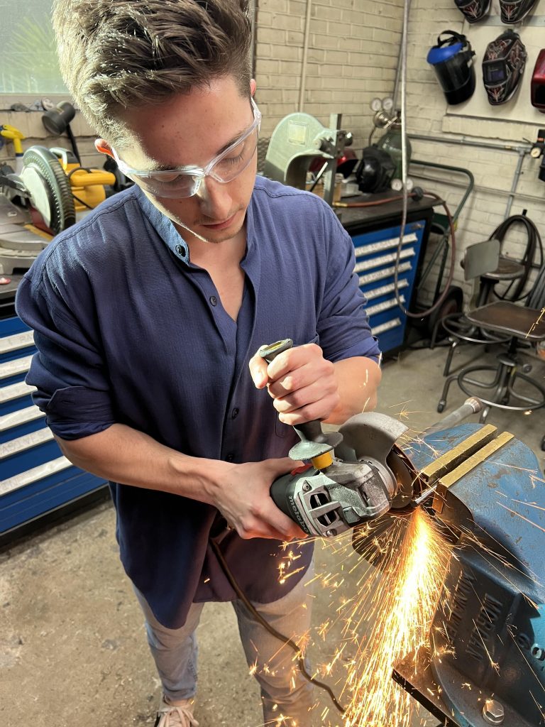
Cutting Rods
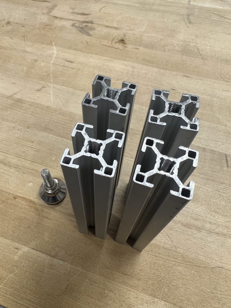
Tapped AI Extrusion
Assembled Gantry Structure
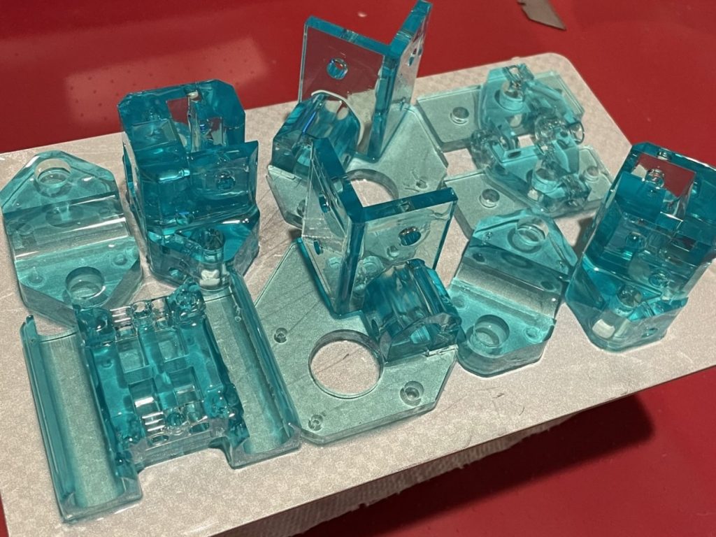
3D Printed Gantry Mounts
We have a preliminary model for the sensor housing on the gantry. This will help us to better visualize how the sensor will fit on the gantry and make any necessary modifications before finalizing the design. Moving forward, our plans for the next week include printing the sensor carriage for the gantry, working on pseudocode for the sensing system, testing PCB function on samples and troubleshoot if needed, and checking that the speed of the stepper motor matches the measured speed of the cart tester.