Greetings readers! We have some exciting updates to share with you regarding our ongoing project.
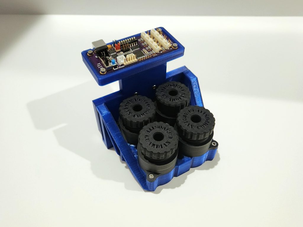
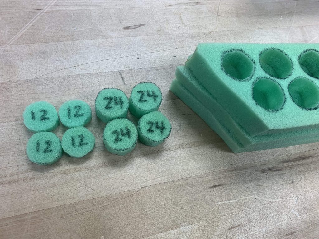
Firstly, we’ve corrected some soldering issues with our PCBs and continued working with our sensor code and device integration. We’ve also completed the design for the sensor housing and have successfully printed the sensor casing to attach to the gantry. In addition, we’ve cut foam cylinders to act like springs within our sensor casing to provide constant pressure onto the sensor during use.
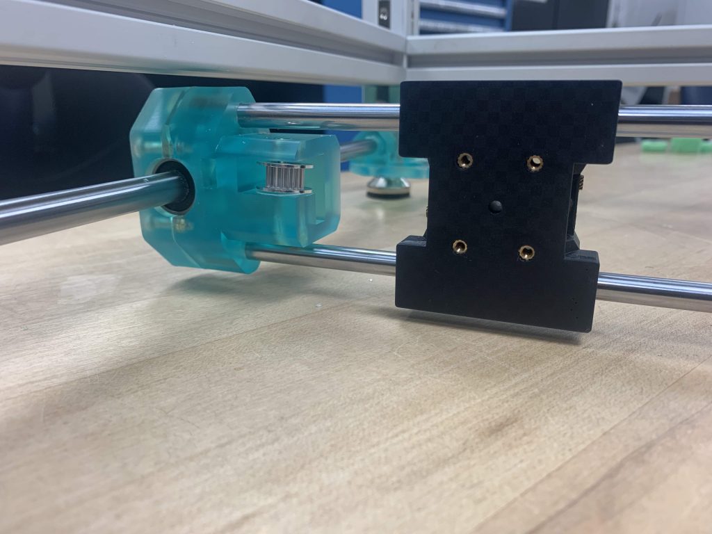
In preparation for our upcoming prototype inspection day, we’ve made some modifications to the gantry. Specifically, we’ve enabled manual movement of the attached sensor housing as electronic issues were causing excessive vibrations. This modification not only resolves the issue of excessive vibrations, but also allowed the sensor housing to be closer to the scanning surface. This will require less 3D printing material for the sensor housing to be close to the prepreg surface.

As for our plans for the upcoming week, we aim to remake test samples and run them with individual sensors for cleaner electronic data. We will also continue to test and troubleshoot our inductive sensor code with the device either this weekend or early next week. Furthermore, we plan to continue work on our motherboard code and begin testing with the PCB. Finally, we will be verifying the iolab cart speed with the gantry movement.