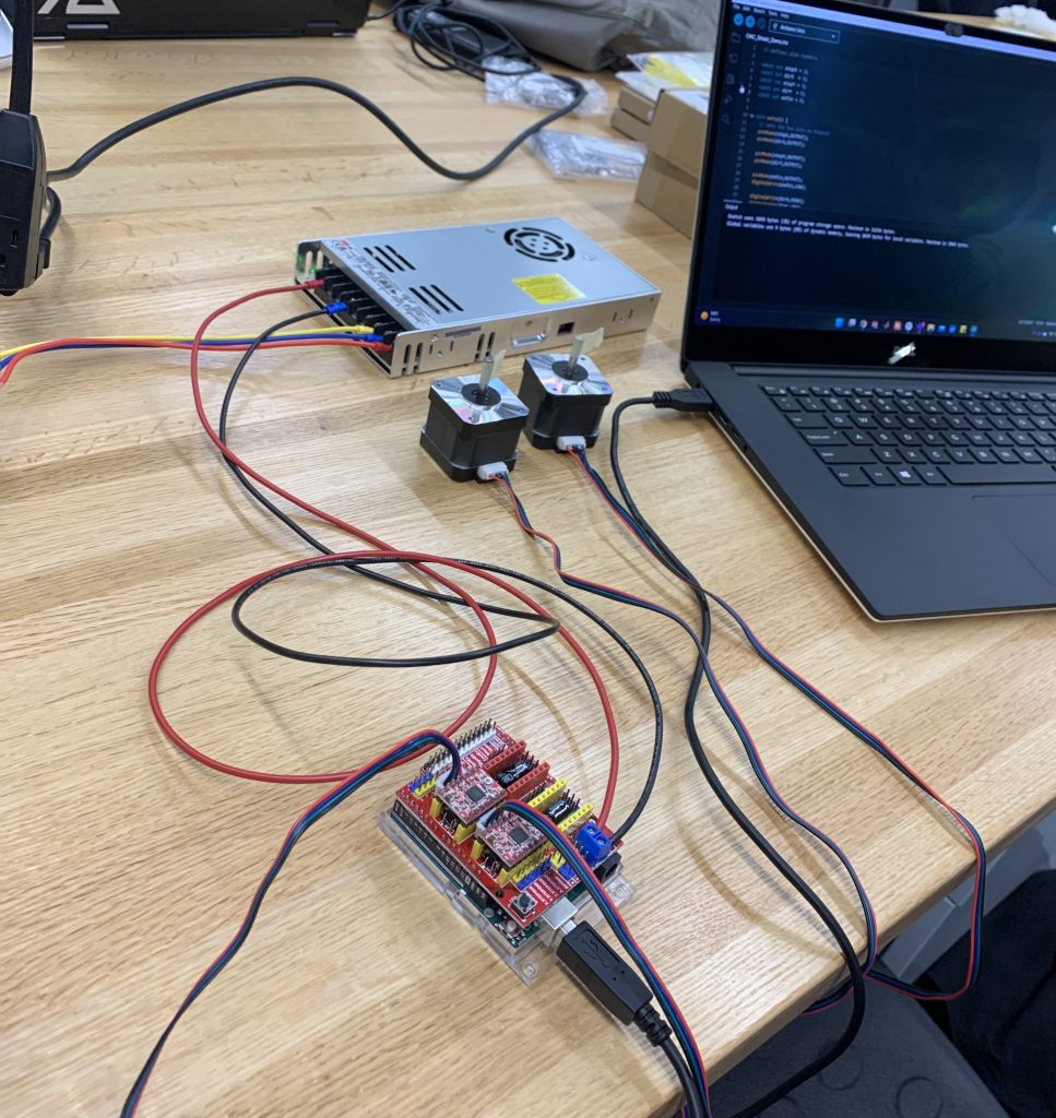
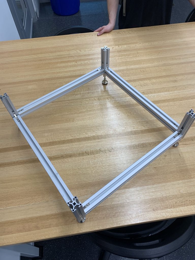
With the QRB 2 coming soon, we wanted to ensure that everything is functional from the components we purchased. We have assembled the basic gantry structure and ensured stepper functionalities. We have also designed human error testing and ordered parts to investigate variations in speed and pressure of a handheld device. This will help us to better understand the variability of our device and make any necessary modifications to ensure its accuracy. In addition, we had an hardware engineer review our PCB designs. After validation from the expert, we placed the sensor PCB purchase orders (POs). With the expert’s feedback, we are confident that our sensor PCBs will function as intended.
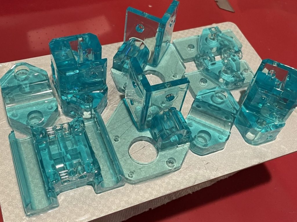
We have a preliminary model for the sensor housing on the gantry. This will help us to better visualize how the sensor will fit on the gantry and make any necessary modifications before finalizing the design. Moving forward, our plans for the next week include printing the sensor carriage for the gantry, working on pseudocode for the sensing system, testing PCB function on samples and troubleshoot if needed, and checking that the speed of the stepper motor matches the measured speed of the cart tester.