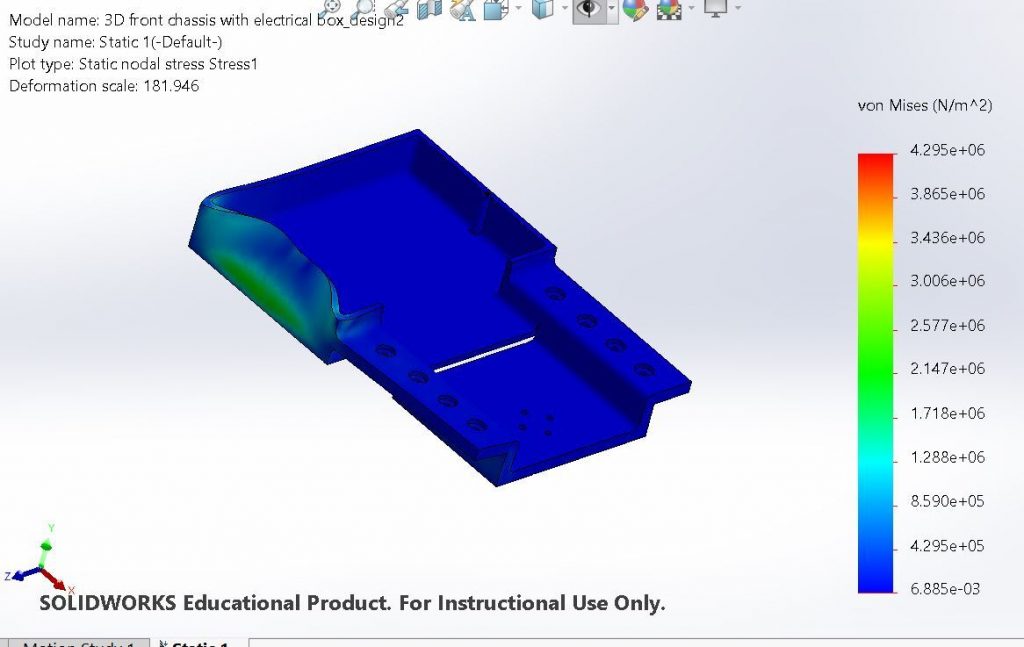
This week the Addtronics team has hit the ground running by beginning to implement feedback given during QRB1 and also begin the next phase of testing. Picking up from QRB1 further research has been conducted to determine if the strength of the 3D printed interface will be sufficient for the project. Additionally the robotic arm has been covered using foam to protect it in case there is any fall. This should protect the components from large damage if a fall were too occur. Additionally, the raspberry Pi was updated to use the hardware gpio/clock in sides processes. Also, the GUI has been further updated to be more user friendly. Aside from this we have started setting up tests and updating designs and parts depending on the outcomes of testing. So far we have begun unit testing to examine the performance of the integrated system.
This week the Addtronics team prepared and presented for qualification review board 1 (QRB1). This presentation served to communicate our progress so far as well as our next steps. We received a lot of very useful feedback that will be considered as we continue realizing our design. The presentation included updates regarding the new electronics set up, testing of the motor controllers, new 3D printed interface design, and 3D printed adapter parts for the linear actuator that were mentioned in last weeks blog post.
Updates
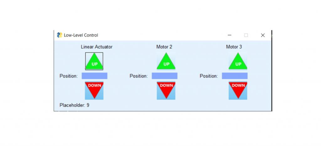
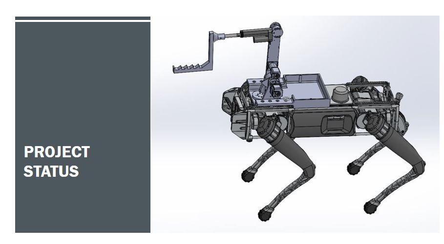
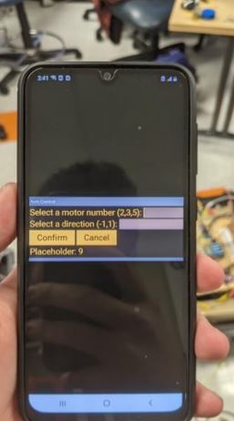
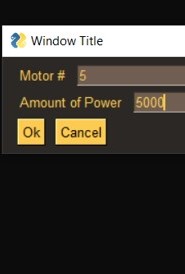
Additionally, we have created a GUI that has been deployed to a smartphone to facilitate controlling the motors (seen right). We have also finished printing the new interface which has now been mounted onto the quadruped. Moving forward we plan to conduct extensive testing of individual systems such as the arm motor reliability, arm payload, and network to ensure these components function individually. Afterwards we plan to conduct more cohesive tests such as lifting the weighted mock box lid and quadruped maneuverability test.
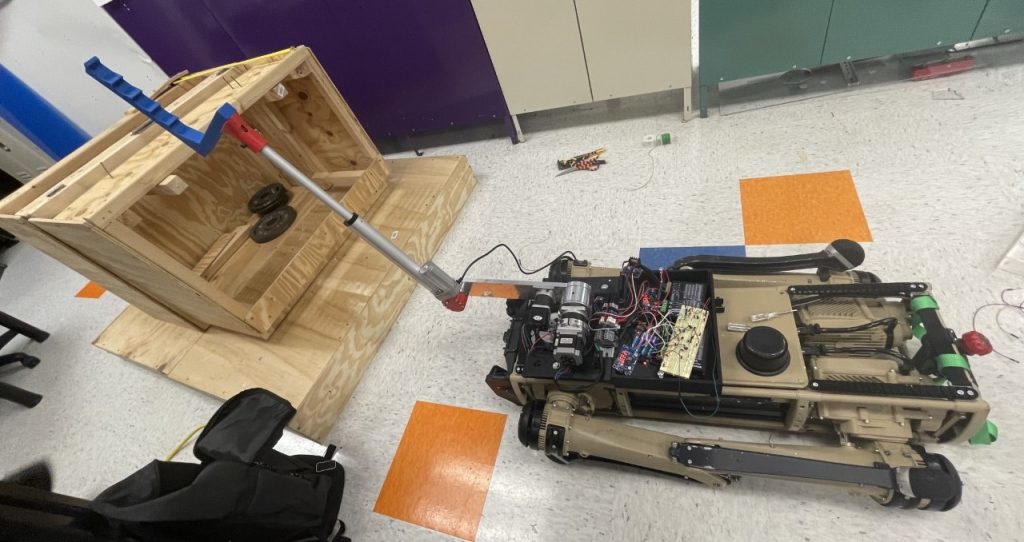
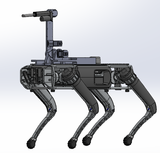
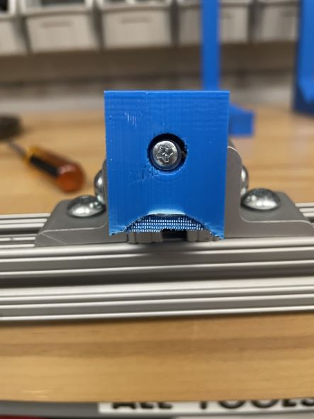
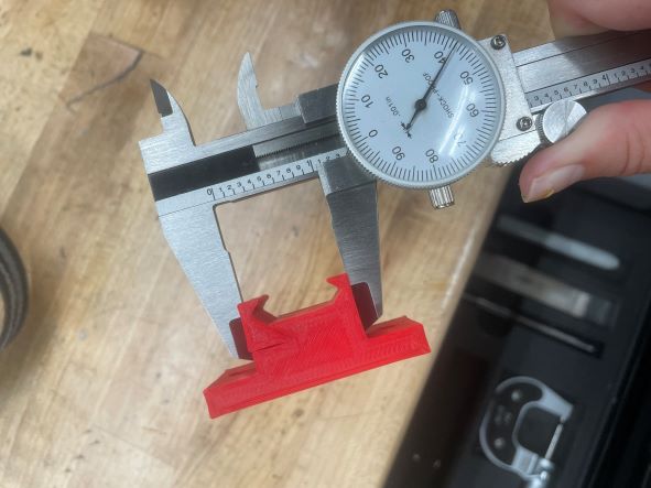
This week the Addtronics team got right back to work by continuing testing and holding our regularly scheduled weekly liaison and coach meetings. Since last week we have worked to improve various components to interact better with other parts of the product. The adapter part and new 3D printed interface are both currently being revised based on testing results to better suit the other components. Aside from this, we have also conducted testing using a variety of motors to determine which motor will help us meet our desired lifting goal while still functioning well with the other electrical components. Currently, we are finalizing a decision of the most appropriate motors to then properly map the dimensions needed for the interface (as can be seen in the second picture).
As components are individually replaced and improved, we have also begun setting up for a cohesive weight test using all of the components. We plan to use use the mock box to conduct the weight test and have rebuilt it to accurately model the weight of a transformer pad found in the field. Additionally, the weight of the mock box is easily removeable which will allow for testing of various conditions. Lastly, we have begun preparing for our qualification review board 1 (QRB1) presentation. We have begun sorting through all of our data and compiling it in a way that best conveys the information to our audience. The presentation will include highlights of what we have accomplished so far, the things we are currently working on, as well as our plan moving forward.
After a nice and refreshing holiday break the Addtronics team is back in motion and eager to implement new ideas! Coming back from the break included the opportunity to update our organizational strategies and revise our plan based on our progress so far. We were able to modify old goals to better fit our new needs as well as develop a better meeting plan to keep all of our members up to date with day to day changes.
What’s New
The aforementioned acrylic interface has been built and used for simple testing. We determined that the acrylic was much too flexible and shattered during one of our tests. Aside from the new acrylic interface we’ve replaced the forearm of the robotic arm with a linear actuator. The linear actuator will help reduce the total weight of the robotic arm as well as allow for better control since we had previously reduced the arm’s degrees of freedom. Additionally, we have replaced the motor which provides the lifting motion of the forearm for a much stronger motor in order to achieve a bigger payload with the robotic system. We’ve begun initial testing using the new motor and linear actuator which can be seen in the video at the bottom!
Future Work
After discovering the acrylic interface was not sufficiently strong, we are now planning to create a new smaller interface that will be entirely 3D printed with a fill density and thickness strong enough to sufficiently hold and protect the components. A new 3D printed interface will also significantly reduce the load experienced by the quadruped which will facilitate its actions. Due to our change to the linear actuator, we are working on creating an adapter part to mount the end effector onto the linear actuator. This part will allow for the end effector to be modular and gives the option for interchangeable end effectors in the future. Additionally, we plan to continue developing the GUI to allow for cohesive control of both the arm and the quadruped.
Linear actuator and motor testing – Song: Pump It by Black Eyed Peas
Addtronics team after System Level Design Report presentation with Florida Power and Light liaisons Kyle Bush (left) and Troy Lewis (right).
This week the Addtronics team tackled the Systems Level Design Report (SLDR) presentation. The event was held on Tuesday December, 7th in the Reitz Union where many of the teams’ liaisons and coaches attended their presentations. During this presentation we covered main aspects of the progress of the project such as the updated technical performance measures, functional architecture, prototype design, and future work for the project. As recommended by our sponsor, Florida Power and Light, we will focus on the scope of the project first before exploring other ways the project can be improved. Overall, the presentation went well and we received some great feedback from our sponsors and from the audience. Our sponsor agreed with our progress so far and encouraged us to continue working on the project.
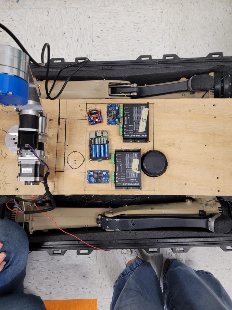
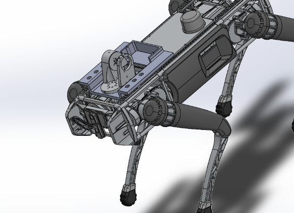
In the following semester, we will continue to work on the software, hardware, and electronic components. So far, we have continued developing end effector designs and have completed end effector failure testing (pictured below). The best end effector to support the maximum weight of the lid with minimum bending has been determined through these tests. This end effector is lightweight and uses a ratcheting mechanism to avoid slipping. Additionally, a new interface has been developed that will lower the center of mass of the arm system (pictured below). This interface is made using sheets of acrylic to improve rigidity and provide a sleek design. The electrical components have also been reorganized as seen in the picture below. This reorganization helps with debugging and allows wires not to get caught or loosened. With the improvement of the electrical box, these components will be slightly shifted, but their initial organization makes this more manageable. Lastly, we will continue developing the graphic user interface (GUI) to make it more seamless and user friendly than our current design (pictured below).
Broken end effector from failure testing
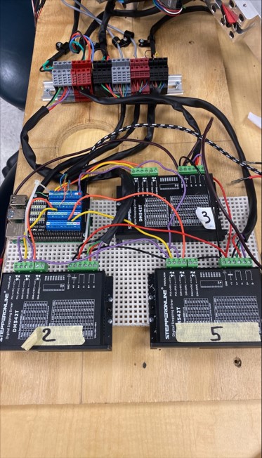
Updated organization of wiring
Current GUI developed
New interface design developed made from acrylic sheets
Gallery of pictures detailing our progress towards future work
This week the Addtronics team tackled the peer reviewed Systems Level Design Report (SLDR) presentation in preparation for actual SLDR presentations that will be occurring next week. We presented general information about our project and sponsor as well as our road to prototyping and testing to showcase all the work we have done thus far. We received some fantastic feedback and questions from our peers to help us improve our presentation next week in areas such as figures, formatting, and detailed descriptions. Overall, we were able to present a lot of relevant information in a clear and concise manner that encouraged the audience to ask some great questions about our future plans and implementation strategies.
Following our feedback from prototype inspection day, the team has been hard at work with implementing new and modified designs, evaluating these changes, and planning our future work.
In terms of software there have been updates in the software used to control the arm so that it operates faster and is more maneuverable as well as updates in the Graphic User Interface (GUI) getting us closer to a more effective and user friendly design. Looking forward, we plan to combine the arm and quadruped software to be controlled through one user interface that will be accessible through a mobile device. We also plan to integrate some semi-autonomous functions of the robot such as a one button command to open the transformer lid smoothly.
As far as electronics, our electrical engineers have removed unnecessary stepper motors and stepper drivers from the arm, organized the arm’s wiring, and replaced the 2 microcontrollers originally installed on the arm with a Raspberry Pi microprocessor. The reduction of components overall reduces the complexity of the arm as well as reduces the weight loaded onto the quadruped. The wiring was organized by color coding wires and securing them using heat shrink and DIN rails which allow for easier debugging as well as provide protection from external factors. Looking forward, we plan to power the arm directly from the quadruped, change out the main lifting motor for one that can provide a greater torque, explore incorporating a linear actuator, and add sensors onto the end effector that will be used.
Lastly, our mechanical engineers have been hard at work implementing and testing some new hardware designs. So far, new metal picatinny rails have been implemented for improved rigidity of the interface mounting, new interface design and materials have been been created and purchased, respectively, and multiple new end effector designs have been manufactured. Fabrication of the new interface designs will begin soon and will be followed by extensive interface testing to determine which design best meets the project criteria. Currently, there are 4 different end effector designs with unique geometries that have been manufactured. While 3 of those end effectors have been 3D printed, one is unique in its entirely metal and modular design. The video below shows a time lapse of one of our engineers manufacturing this metal end effector which is made out of 1 inch 80/20 (extruded aluminum). Looking forward, we plan to improve the rigidity of the electronics box by reinforcing it with carbon fiber, continue testing improved versions of the most successful end effectors, and develop back up clamping methods.
80/20 End Effector Manufacturing Time Lapse – Song: Aguardiente y Limon by Kali Uchis
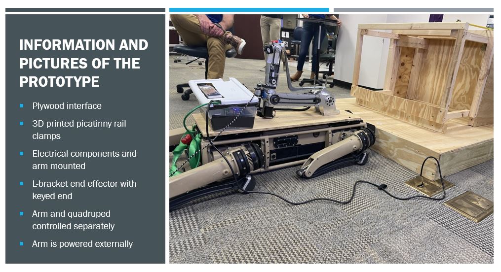
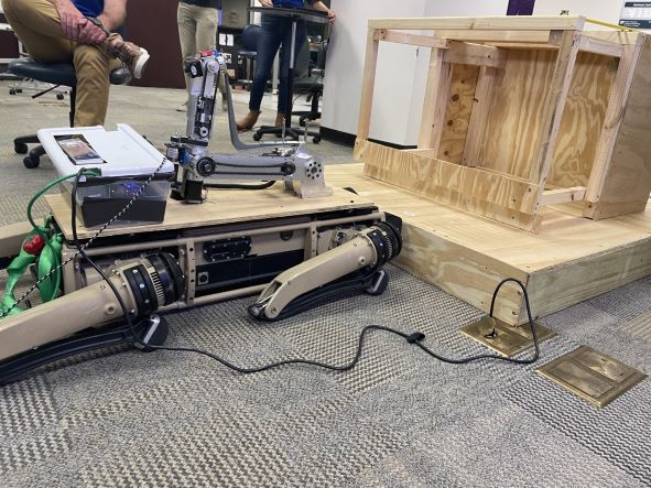
After completing more extensive testing of the integrated components, the Addtronics team dove right into prototype inspection day. For our demo, we gave a quick introduction of who we are and the project our sponsor has tasked to complete throughout this course which is to open the lid of a single phase pad mounted transformer by integrating a quadruped and robotic arm. We then highlighted some of the key features of our design and jumped into a demonstration of the arm physically lifting the lid of our transformer pad mounted test box. For our design, the quadruped will be aligned in front of the transformer pad and will be lowered to the ground as seen in the picture above. Once on the ground the robotic arm will extend from its stowed position out and position the end effector under the lip of the lid. The lid will sit in the slotted portion of the end effector to reduce slipping and then the robotic arm will be moved to lift the box initially as seen at the end of the video below. The video below highlights some of the specific tests we conducted leading up to prototype inspection day and shows how the quadruped will be walked over to the transformer pad and lowered to then allow the arm to lift the lid.
Prototype Day Demo Video
Looking Ahead
Throughout our journey in preparing this demo for prototype inspection day we learned a lot through our testing and received a lot of useful feedback as well. Moving forward we plan to explore design variations for the chassis using a different material, use stronger picatinny rails made of a different material, as well as explore different end effector options. For the electrical components we plan to do more testing on the motors to make them more efficient, further organize the electrical box, and integrate the quadruped to directly act as the power supply of the arm. Finally, we plan to stream video of the quadrupeds point of view using the camera on board the quadruped and incorporate a GUI that can be used on a mobile app to control both the arm and quadruped using the same controller. Overall, there is still quite a bit of work to be done to make our design stronger, more reliable, and more user friendly. We look forward to sharing all our progress in accomplishing these goals with you!
Continuing on from the previous week, the Addtronics team has continued to develop their prototype inspection day plan to share with the prototype day judges as well as our coach and liaison. This week we have continued advancing our software and electrical components as well as implementing improvements for hardware after testing. In the last iterations of testing, we discovered a drawback in one of the robotic arm motors. After more extensive testing we identified the motor was faulty and quickly replaced the motor to improve the overall functionality of the design. We have also continued extensively working on the code to control the robotic arm as well as the development of the graphic user interface (GUI). This week we thought we would share a time lapse video (seen below) of some of our engineers in action working on some of these software components.
https://youtu.be/rLyNLmhmz04
Software Engineering in Action
As mentioned earlier, aside from software there have also been major improvements in hardware and procedure. During testing last week, we determined the quadruped’s inability to adjust for the added weight of the robotic arm and electrical component box (which can be seen in the motion of the quadruped as it stands up in last weeks video). In the previous week, the quadruped would stand lifting its front side first and then swinging up its back side which did not properly distribute the additional weight. This week we were able to incorporate payload compensation so that the quadruped stands up in a more aligned fashion (as seen in the video below). Implementing this approach will largely mitigate the risks of any falls of the quadruped which could potentially damage the arm and/or electrical components.
More Standing Quadruped Testing
As we continue into our final days before prototype inspection day, we plan to do further testing with end effectors both for demonstration purposes as well as some long term goals for the project. We will be rehearsing our demo presentation to adequately showcase all of the key features of our design as well as make it an engaging and fun experience for the audience!
Outreach
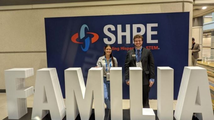
Outside of the scope of the project, our team is also involved in various organizations. This week two of our members attended the Society of Hispanic Professional Engineers (SHPE) 2021 National Convention where they got to network with other young professionals from engineering backgrounds. Want to learn more about other organizations we’re involved in? Check out the ‘Meet Addtronics’ tab to learn more about each team members affiliations!
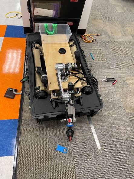
This week the Addtronics team has been hard at work with prototype building and prototype testing. Continuing from our milestones and goals from the previous week, we’ve been able to incorporate the majority of our prototype plan to increase time for testing and modifications. We first reduced the arm from 6 degrees of freedom to 4 degrees of freedom by locking two of the motors in place and removing their controllers. Upon doing this we were then able to condense the electrical components. The electrical components were then organized and mounted into the new plastic electric box prototype to be mounted onto the interface. The wires were further organized and protected using nylon conduits to avoid tangling while the robot was operated. Additionally, this week we constructed the wooden interface prototype and printed the picatinny rails for mounting the interface onto the quadruped. After the interface was mounted we were able to successfully mount the arm and electrical box into the interface.
This completes the majority of the components we plan to present for our prototype day demonstration! We are continuing working on controlling the arm using the Raspberry Pi and adding that to the electrical box. Once the Raspberry Pi has been fully integrated, we will be able to begin testing lifting the mock transformer pad lid and making any necessary modifications. In the meantime, we have begun some initial testing to observe the weight the quadruped can hold while staying stable (seen in the video below). The weight was mounted in a cantilevered fashion to simulate the moment created by the arm extension when lifting the lid in the field.
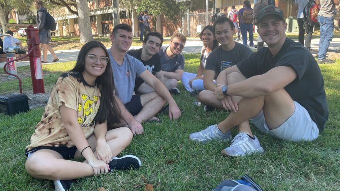
This week the Addtronics team has been hard at work , but who says work can’t be fun? Despite all our progress, the team still got the chance to with enjoy a nice Florida fall day together (see above picture)! This week we are extremely excited to share with you even more progress with testing and prototyping:
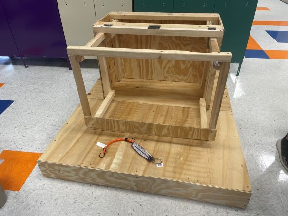
Continuing from last week, we have updated the mock box to be more representative of a real transformer pad by adding an accurately dimensioned base and have replaced the lid with a more lightweight and modular design (pictured left). The modularity of the lid will allow us to progressively increase the weight of the lid as we test the lifting capacity of our integrated system (coming soon).
Additionally, we have begun prototyping our physical interface to integrate the robotic arm to the quadruped. We plan to use the picatinny rails shown to the right for mounting of the arm base. More rails will be printed to begin base construction soon!
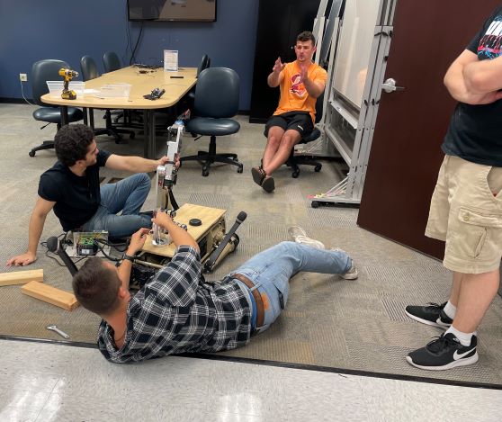
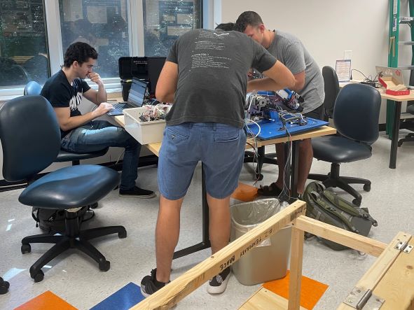
Aside from prototyping for integration and testing, this week we have all shifted our focus to the robotic arm (see some of our team working on the arm in the picture to the left). Currently, we plan to reduce the arm from 6 degrees of freedom to 4 degrees of freedom. This reduction will help reduce the total weight and space that will be taken up by the electrical components housed on the quadruped. This reduction will also help improve rigidity and strength of the arm during the lifting process.
In continuation with the arm, we plan to further reduce electrical components by controlling the arm via a Raspberry Pi. Aside from reducing components, this will greatly simplify the code and decrease lag time to better control overall. We have begun some preliminary testing of controlling the arm and lifting the mock box lid using the Raspberry Pi which can be seen in the video below.
Song: Chamillionaire – Ridin’
Aside from physical testing and design advances, we are currently working on developing our demo for prototype inspection day. We plan to incorporate a lot of the tested features and give an accurate display of the capabilities of our design. We have created a schedule with tasks to ensure we meet all our expectations for our prototype which we look forward to sharing with you all!