Blog Posts

Top Dog

Picture taken with quadruped camera

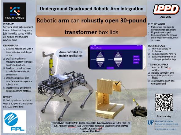
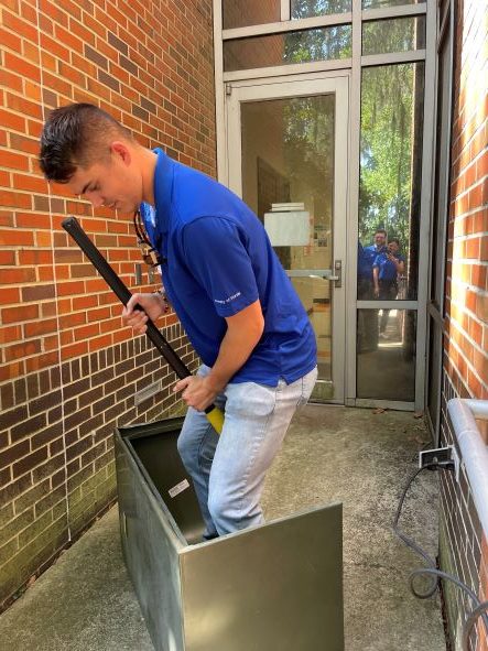
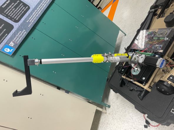
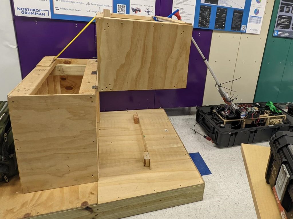
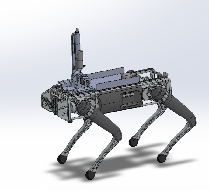
This week the Addtronics team took on presenting and giving a demonstration as part of FDR (final design review). We first gave a presentation outlining our scope of work and a broad path of how our project was accomplished throughout the course of the year. We highlighted some big failures that led to big successes and the big learning journey that we each went on individually and as a team. Following our presentation we headed to our booth which included our team poster and our live demo. The poster gave a brief overview of our project with specific items such as our scope of work, our goals, and the specifications of our design. Over to the side, we were able to show people our quadruped walking over to the mock transformer box, sitting down, and extending its arm out to lift the lid. We were able to conduct this demo repeatedly and show the live video stream inside the transformer box using the quadrupeds live video feed. Overall, we had a fantastic year learning and interacting from and with each other and are excited for what the future holds!

Addtronics promo video

Puppy Love

Addtronics poster first draft

This week the Addtronics team has been focusing on preparing for our Final Design Review (FDR) which will be held next week. In order to prepare, we have been hard at work on elements such as our poster (pictured above), promotional video, presentation, and demo. The poster and promotional video are both meant to give an overview of our entire project including concepts such as the issue we are solving, how we are solving it, and the benefits of our design. The presentation provides more insight on specific tasks completed, goals met, and decisions made throughout the process. The demo will serve as proof that we have completed our scope of work entirely and will help the audience visualize our components and how they work together.

Additionally, we have continued working on our software and controller approach for the arm. We have reduced the number of commands needed to fully open the lid after positioning the quadruped to 5 commands thus making our system more user friendly and easy to operate. We have also received an actual transformer box lid from Florida Power and Light to use for our FDR demo. We have mounted this lid onto our mock box to serve as a more accurate representation of how our design will work in the field. We are very excited to share our realistic demo with you all during FDR next week!

Howling Success

Arm quadruped assembly

This week the Addtronics team has been hard at work updating parts and features. The new end effector adapter bracket and revised end effector have been installed and tested with a 100% success rate! he new end effector adapter bracket is a modified off the shelf part made of aluminum in order to provide greater strength and support when lifting the lid. The end effector was revised in order to be compatible with the new adapter and was made thicker to handle the weight of the lid better. Additionally, limit switches have been implemented in order to update the systems operations and GUI design. The GUI now displays commands to automatically stow and deploy the arm which have been fully implemented. The arm reaches completes the stow command by fully retracting the linear actuator and rotating the arm back fully without crushing the electronics box lid. The limit switch detects when the arm has made it to this position and establishes that the command has been completed. Deploy works in the opposite manner where the arm rotates forward until the end effector makes contact with the base of the transformer pad. A sensor indicates when contact has been made and the arm is then instructed to stop rotating.

Moving forward the Addtronics team will continue to refine and condense parts as well as simplify the operational commands of the system. This will allow for easier assembly, installation, and control of the system. Additionally, the team will continue to work on the Final Design Report (FDR) as well as the accompanying presentation, poster, and video to fully explain the functioning system in a way where it could be implemented and modified by anyone.

Dog with a bone

Tool room equipment

This week the Addtronics team has been hard at work making final modifications to the final functional design. These modifications include refining parts to make them more aesthetically pleasing and reliable. So far we have refined the interface and reinforced it using steel rods. This new interface was designed to withstand higher loads and avoid breakage under unusual circumstances. Additionally, we have modified an off the shelf aluminum part to replace the plastic adapter part. This part greatly improves the rigidity of the design as this part holds a large stress concentration. The aluminum allows it to resist the large concentrated stress and improves its lifespan. This part was manually machined in order to properly hold our final end effector design which is thicker and stronger than the one used in testing in order to provide additional support. In terms of electronics, we have incorporated a flashing beacon to indicate when the quadruped is being operated out in the field and begun incorporating sensors. The beacon is visible in inclement weather to nearby service men and citizens. We have installed a gyroscope sensor in order to tell when the robotic arm assembly has made contact with the lid. This will allow the lifting motion to be carried out more swiftly and pressing less buttons by calculating some of the lifting trajectories that will be deployed at the push of one button.

Moving forward we plan to continue further organizing the mechanical and electronic components so they are tidy, easy to understand, and reliable. Additionally, we plan to make the GUI even more user friendly by implementing the one button push approach using the sensors.

Dog show

This week the Addtronics team tackled prototype inspection day (PID). As mentioned previously, we first gave a short introduction about our team and project and then showed a video of the quadruped walking up to the transformer box and positioning itself. We showed a video rather than doing a live demonstration due to not having yet received back our quadrupeds leg. Thus, the video would serve to show the initial portion of our demo. Next, we transitioned to the live demo which involved the quadruped laying down on the floor positioned in front of the transformer pad lid and lifting the fully weighted lid. The arm (now controlled by the GUI on the smartphone) was operated by us during the demo where the lid was lifted in small increments until reaching a fully open position.

Moving on, we plan to revise some mechanical designs to make them more aesthetically pleasing now that we have ensured their functionality. This includes having a finalized interface, adapter, and end effector piece. We plan to do something similar with the wiring where we will organize and mount the electronics more neatly now that we have ensured reliability. Additionally, we plan reduce the number of commands that need to be sent to the arm to open the lid and plan to make it a fluid motion. We will implement this by adding several sensors to indicate parameters such as position and acceleration to gain an idea of the current environment.

We are excited to share our live demo below!

Mock box testing using full weight of 30 lbs

Barking up the wrong tree

New revised interface

This week the Addtronics week has been steadily preparing for Prototype Inspection Day (PID) which will occur next week. Here we plan to demonstrate our prototype to judges who will be able to ask questions and provide us with valuable feedback on our design. Since we have not yet received back the front left leg of the quadruped after being sent to be repaired, we have planned to open the mock box lid entirely using the arm. Thus, we plan to first show how the quadruped would walk up to the transformer box by displaying a video. Then, we plan to physically demonstrate our prototype lifting the lid. The quadruped will start laying down in front of the mock transformer box (in the position it would end in the video) and we would begin control of the arm via the GUI. We will show the judges the GUI and how it is being controlled in order to obtain their feedback on how user-friendly it is. We will not be allowing the judges themselves to use the GUI as improper control could lead to hardware damage and poses a safety risk to those nearby. We plan to control the arm using the GUI to completely lift the lid thus demonstrating our scope of work.

In order to ensure our PID demo is reliable we have each been working on updating individual aspects of our prototype. Physically, we have revised the interface to be stronger and more durable. To do this the geometry was changed to bear the load of the lid better as well as adding slots for steel reinforcement bars. Additionally, another iteration of a steel reinforced adapter has been manufactured to avoid breaking when lifting the lid. Lastly, the GUI has been successfully deployed onto a smartphone where testing has confirmed that the Raspberry Pi is receiving the command signals sent from the phone to control the arm motors. Moving forward we plan to continue unity testing and increasing the amount of weight that the robot assembly can lift. We will also be adding a flashing light to indicate when the robot is turned on for visibility in poor weather conditions as well as to potentially scare off dangerous wildlife.

Big stretch

Lid test using only the arm

Continuing from last week the Addtronics team has worked hard to implement modifications needed (stemming from previous testing) as well as incorporating feedback and suggestions that were received during QRB2 last week. With certainty that the new motor and linear actuator worked reliably using the lightest configuration of the mock box we began adding weight to the mock box lid to simulate a payload test in a real environment (pictured above). The results showed that although the motors were now fully capable of lifting a heavier, the 3D printed components were not rigid enough to support this weight. During testing the linear actuator adapter piece and brackets used to hold it in place both broke (seen below). This corroborates our original idea that the ABS plastic parts would not be strong enough. To avoid increasing the weight of the overall assembly we have decided to create hybrid parts that are still 3D printed but have metal reinforcements, such as steel sheet metal and steel rods) within them. Several versions of these parts are being made for testing and to have extras if necessary. to lift lid (see picture). While the physical interface continues to be updated the electronics have now been successfully mounted to a perforated crossover board which avoids having to rewire and secure the electric components each time the interface is updated. This mitigates the risk of of electronics failing due to improper wiring. Additionally, this makes debugging easier as the components are removable from the rest of the assembly.

This week the team has also begun GUI testing which has shown the need to improve the network being used. The network is being modified so that the app (once deployed on the phone) can interact directly with the robotic arm and require no other intermediary device. Additionally, the team has begun exploring how to implement a “one-button-push” approach to lifting the lid that will require less skill and coordination from the user and therefore will be easier to use. Currently, the team is exploring using the camera stream on the quadruped as well as various sensors in order to implement this approach.

Let sleeping dogs lie

Quadruped with new linear actuator

This week the Addtronics team did QRB2 (qualification review board 2) where we received some incredibly valuable feedback regarding our project. We presented updates regarding the tests we’ve conducted since the last QRB (summarized in previous blog posts) and stated our findings as well as how the project has shifted due to those results.

So far, we have updated the GUI, installed a new linear actuator with a longer stroke, installed a new motor that is able to provide more torque, installed a new motor controller to use with the larger motor, and installed level shifters to draw the appropriate amount of current to power the new motors. A motor test has been conducted which preliminarily shows the new linear actuator and motor will be able to lift the lid without needing additional help from the quadruped. Another finding from the motor test has shown the current interface design is too weak to sustain the force produced from lifting the lid.

We are currently exploring multiple designs to strengthen the interface so it will not break when lifting the lid and will begin to manufacture them soon. As the interface is being updated, we have also begun moving the electronics onto a perforated crossover board for easy removal from the quadruped while reducing the risk of accidentally damaging the functioning wiring. Once the new interface is installed, we will continue conducting tests to determine the reliability of the interface-arm pair. We are currently focusing on the functionality of the arm as we wait for the front left leg of the quadruped to be repaired. Once the leg has been fixed we will expand our tests to include the quadruped.

We didn’t start the fire…

This week the Addtronics team has worked steadily on implementing changes in order to improve the working prototype. Specifically, we have been applying DFT (design for testing) principles in order to make sure we meet the main goal of our scope of work. During our lid test last week, we determined that the arm alone is not able to lift the transformer pad lid. We have since then planned to have the quadruped assist with the lifting motion by rising from a crouching position to a standing position while holding the lid. In preparation to do the combined lifting, we have been testing the quadruped initializing and standing up with the arm mounted. It was crucial to determine the standing up motion was reliable with the additional weight to ensure the quadruped will not roll on its back and damage the electronics and hardware that are mounted as we have seen happen before. After ensuring reliable motion, we moved the mock transformer box outside for testing in a realistic environment. Once lined up and in position, we attempted raising the quadruped but the quadruped was unable to stand entirely. The testing seems to have internally damaged a component of the forward left limb of the quadruped which we are steadily working to fix. Looking forward, we are working on alternate solutions to compensate for the low payload achieved by the arm and examine the reason for the limb damage in order to mitigate it in the future.

Short compilation of this weeks outdoor lid testing

Doggy Bag

Motor testing and lid lift testing

This week the Addtronics team continued updating all aspects of the project such as the GUI, mechanical components, and electronics. We have also continued steadily working on testing out our individual components and refining the design to be as effective and simple as possible. Most recently we have begun our lid lifting testing to ensure the components will be strong enough to lift a transformer pad lid. This will also help determine if the mechanical interface and other components are rigid enough and mounted securely enough to withstand the stress produced by lifting. The video demonstrates our initial testing which shows that some adjustments need to be made in order to effectively complete our task. Since this testing, we have been replacing electrical components and modifying our wiring. We have begun soldering and plan to use a printed circuit board (PCB) in our final product to improve reliability. Our current overall goals are to design our final product for testing and reliability. We want to make sure that our product is able to meet the criteria for effective task completion in a reliable manner.