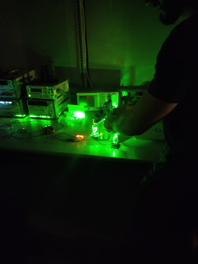
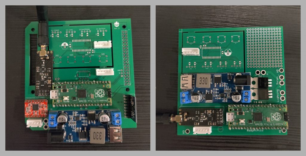
Although it is spring break, and despite the note last week, some progress was made on the progress this week, which the Road Watch team would like to share. Firstly, we believe we have solved our issue with the 1D to 2D LiDAR conversion. Some testing (see the first image below) indicates that the mirror used for the conversion was not large enough, and because the LiDAR we purchased had its transmitter (i.e. laser) and detector off-center, this would lead to some of the beam not being reflected depending on the angle of the mirror. Therefore, we are confident that this issue can be resolved by increasing the mirror size, which we will test next week. Additionally, revision 2 of the Detection Subsystem PCB and revision 1 of the Alert Subsystem PCB were completed and ordered, and arrived this week (see the second image below). The former was redesigned to address some issues and deficiencies of the first iteration, while the latter is needed for Prototype Inspection Day (PID) to show a complete system. As PID approaches, be sure to come back weekly to monitor our prgress.