We have been steadily working on each part of our project and are working on coming together to join the pieces.
One big piece of progress that we made is that we have fully integrated the electronics system and have verified that every part is operating as we have predicted. Additionally, we have some preliminary code that activates our servo motors when the temperature sensors heat up. This is great news for our prototyping team as this is a major hurdle that we have overcome, as now we can make and order the PCB! In terms of our thermo-display, that is what the first picture above is showing. We have 3D printed out smaller models of our idea (left) and the existing housing based off the Honeywell MIMU (right). The next step would be molding the plastic on it and doing more testing.
For our ANSYS team, we have made a SolidWorks model that is able to be used for vibration testing, and have finished our first five simulations. The next step is fully defining our cost function and plugging our numbers into the Kriging model to get our next five parameters to test.
We have been making steady progress on our project every week as we move forward on our project plan. Above can be seen one of the large strides that we made on the prototyping team, fleshing out exactly how we can integrate our system in a realistic way. We came up with the idea of using self torquing hinges like are used in self closing cabinets. The hinge will apply a torque to itself with the spring when in the closed position and will be held closed with some fishing line attached to our servo motors. When the motors are told to activate from our sensors and electronics, the slack will allow the hinge to open fully by itself. This solution is a cheap and low tech solution for opening the flaps that should be easy to integrate.
In terms of progress on ANSYS, we have the the of the first five Latin hypercube models made and our SolidWorks model optimized for ANSYS simulations and easy application of the parameters we are given from our Kriging model. We have done this by both simplifying and making the model more accurate, adding in the areas the flaps would be inlaid whilst filleting parts of the model where the air would create problematic areas in our ANSYS simulation. This has allowed us to make a ton of progress in our simulations, and in turn we have gotten our first points of data that seem to be accurate compared to literature values we found.
All in all we have had an extremely productive week and we are very proud of the progress we have made. We are looking forward to making even more in the weeks to come!
This week, our team made major progress on the simulation side of the project by spending extensive time working in Ansys Fluent. We focused heavily on refining our simulation setup, fixing geometry issues, and finalizing a clear workflow that everyone on the team can follow. Much of this work required close collaboration as we debugged problems and ensured our setup was consistent and repeatable.
One of our biggest milestones this week was successfully running a simulation at 7000 m/s, which marked our first complete high-speed case. We are currently finishing up this initial simulation and carefully studying the results, not just looking at the visuals, but understanding what the data actually means and how reliable it is. Learning how long simulations take, how convergence behaves, and how to interpret outputs has been just as important as running the simulations themselves.
A large portion of our effort went into refining the simulation itself. This included improving the geometry, adjusting mesh settings, and validating assumptions to make sure the results are both relevant and physically meaningful. Rather than taking outputs at face value, we’ve been learning how to critically assess whether the data produced by Ansys truly reflects the behavior we expect under extreme conditions.
This week also highlighted one of the realities of computational simulation: patience. High-speed simulations take a long time to run, and when a simulation crashes late in the process, restarting can be frustrating. These challenges have pushed us to think more strategically about computational resources, and we are now exploring the possibility of moving our simulations to HiPerGator to improve efficiency and reduce runtime.
Overall, this week was a strong step forward. We’re gaining confidence not only in using Ansys, but in understanding its results and limitations. Each iteration brings us closer to a robust, defensible simulation process and we’re continuing to build the technical foundation needed to support our design decisions moving forward.
Meanwhile the prototype team has been quite busy!
Andrew recently built our initial electronic system that comprises of a Inertial Measurement Unit and Thermististors to detect when we are entering reentry, a microcontroller unit(MCU) that will control our system and a step down power regulator that steps our 11V from our battery down to 5V that our MCU can run on. This was a crucial milestone as now we are confident that our basic electronic system that works and we can order our servo motors that will deploy our flaps of our design. We look forward to in two weeks updating you on how we use integrate our servo motors into our electronic design!
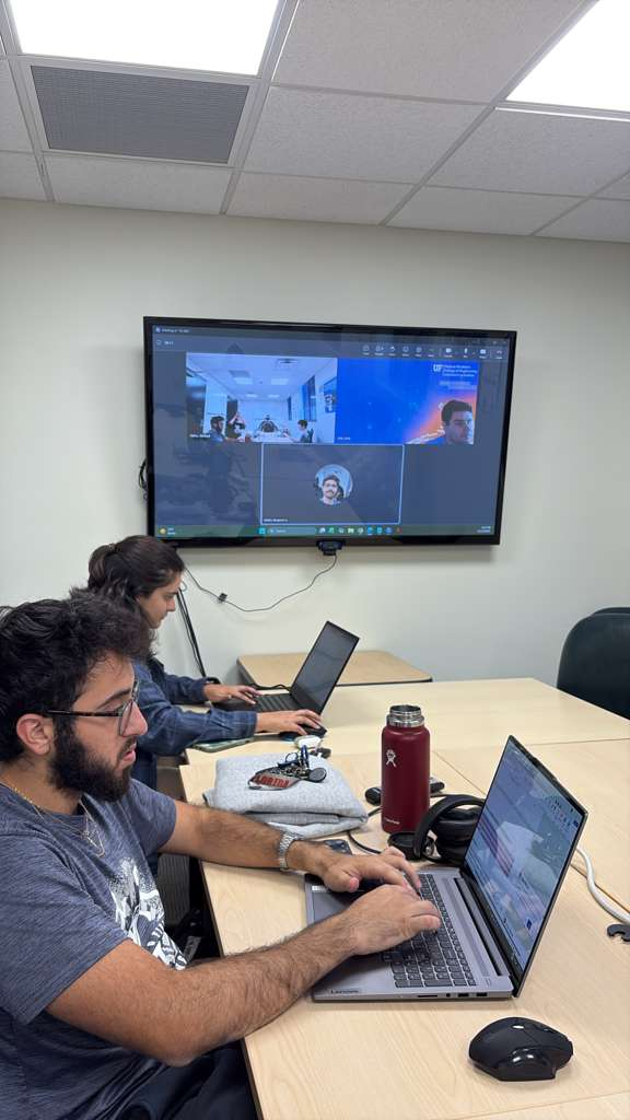
This week, we participated in our first Qualification Review Board (QRB). We presented to Dr. Rick Lind (our coach), Dr. Bruce Carroll, and Dr. Amr Abd-Elrahman. We were evaluated well with some minor critiques regarding the project’s background, uncertainty, and testing considerations. Feedback from these coaches will help move our project along. We plan to incorporate their suggestions into future presentations and assignments.
On the simulations team, Michael is working hard on editng the ANSYS tutorial to realistic conditions. The coaches noted that we must run these simulations using space-like conditions, specifically hypersonic speeds/Mach numbers. We are also investigating the use of SOLIDWORKS for vibration simulations. According to NASA, low Earth orbit re-entry speeds are around 17,500 mph and Mach 25. We are actively looking into replicating these intense conditions in ANSYS.
On the electronics team, parts are being ordered and will soon be tested. Ben has ordered meltable plastic and will test different sources of heat to melt it. There will be two prototypes: one empty meltable shell and one including electronics. This is to physically represent our simulations while also having a prototype that will not destroy expensive electronics.
The project is beginning to shape up, and the future looks bright. We are excited for what’s to come.
In an extremely productive week for the team, we have made an enumerable amount of progress in both of our teams.
Virtual Team: Our virtual team has started the semester very strong, completing a full simulation in ANSYS and getting numerical results that can fit into our machine learning model. Led by Mike’s strides, a complete heat simulation has been achieved and can be seen through the pictures attached. While the accuracy and fidelity of these models are not entirely verified and up to our desired standards, these are amazing first steps for the team and lay an extremely strong foundation to continue this progress throughout the semester.
Physical Team: The physical team has also made a ton of progress. We have acquired almost all of the electronics required to start testing and implementing, as well as having developed an actionable plan for the formation of the prototype and heat demonstration. Yes, that is a new part of the physical team’s objectives, to develop one prototype that demonstrates the electronic capabilities of our design as well as a demonstration that benefits of our design in terms of heat.
With these strides in both of the teams, we expect that the project starts moving even quicker in these upcoming weeks, and we look forward to sharing these updates every week!
Welcome to the second chapter of ARC. A new semester is officially underway, and with it comes renewed energy, sharper focus, and a clear plan of action: execute.
After a long and well-earned break, our team returned refreshed and ready to push this project forward. We recently met with our project coach to align on the semester timeline, define key milestones, and lock in our goals. The message was clear, this is the semester where ideas turn into tangible results.
A Strategic Shift: Two Teams, One Vision
The biggest change this semester is how we’re structuring our work. To move faster and more effectively, we’ve split into two focused sub-teams, each tackling a critical piece of the project:
ANSYS & Virtual Prototyping Team This group is dedicated to simulation-driven design. Using ANSYS, they’ll iterate, analyze, and refine our model to validate performance and guide physical design decisions.
Electronics & Physical Prototyping Team In parallel, this team is bringing ARC into the real world through building the physical prototype while also designing and integrating the necessary electronic components.
By working in parallel, we’re able to test, validate, and iterate more efficiently, ensuring that our virtual models and physical builds inform and strengthen each other.
Momentum, Energy, and Execution
There’s a strong sense of momentum within the team right now. Everyone is energized, aligned, and excited to see ARC move from concept to reality. This semester is all about disciplined execution, turning plans into progress and progress into results.
We’re excited for what’s ahead and can’t wait to share updates as ARC continues to take shape.
This semester marked a major learning phase for our IPPD team as we began developing our re-entry “Design for Demise” solution for Honeywell Aerospace. Our primary objective was to build a strong foundation in ANSYS Fluent, understand the aerodynamic behavior of re-entry conditions, and prepare for the more advanced simulations we will run next term.
We spent much of the semester learning the fundamentals of ANSYS Fluent, mastering how to create and refine meshes, assign boundary conditions, choose appropriate turbulence models, set up solvers, and interpret results. Because real re-entry conditions are extremely difficult to reproduce in the real world, having a reliable CFD workflow is essential to our project. Over time, we became more confident in our ability to set up simulations correctly, troubleshoot issues, and understand why the flow behaved the way it did.
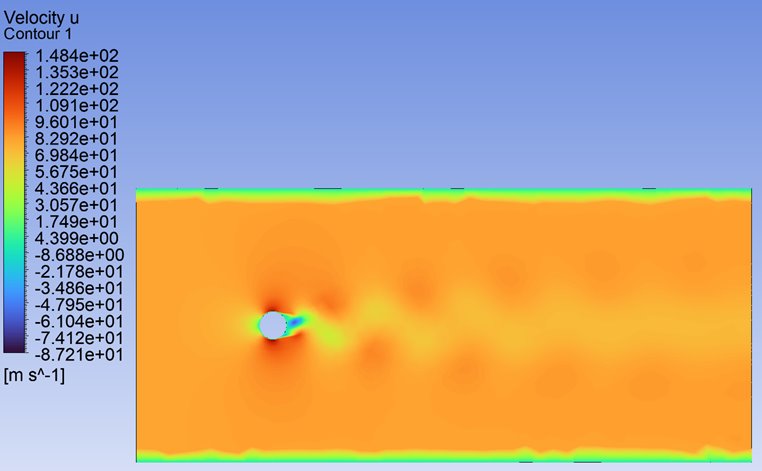
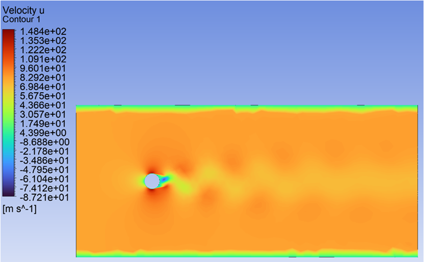
One of the most important milestones was completing a flow-over-a-cylinder proof-of-concept simulation. The cylinder is a classic test case in fluid dynamics, and running it allowed us to validate that our methods were correct. We observed the expected stagnation point on the front of the cylinder and identified alternating vortices known as a Von Kármán vortex street forming downstream. Understanding this phenomenon required us to revisit concepts from fluid mechanics and study how vortex shedding works and why it appears at certain flow regimes. This project strengthened not only our technical skills but also our ability to interpret and explain physical results.
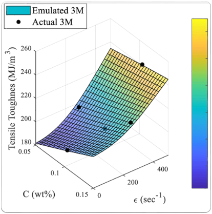
Another major achievement this semester was developing a Kriging surrogate model to optimize our design parameters before running full CFD simulations. Since high-fidelity simulations are computationally expensive, we needed a systematic way to determine which configurations were worth testing. To do this, we first identified the key geometric and physical variables of our design. We then used a structured set of sample points to train the Kriging model, which created a predictive map of how different parameter combinations influence performance. This model helped us narrow down the design space and select the most promising configurations for next semester’s simulations. Building the model taught us how surrogate modeling can guide engineering decisions and allowed us to work more efficiently with the resources we have.
We also prepared and delivered our System Level Design Review. For the SLDR report, we wrote detailed sections explaining how ANSYS works, what simulations we ran, how the simulation process functions, and why this software is crucial for our mission. Presenting this information pushed us to think carefully about clarity and communication. Many of us realized the challenge of presenting technical information smoothly, and the experience gave us insight into how we can improve our presentation skills going forward.
Throughout the semester, we grew significantly as a team. We learned how to divide tasks, explain complex ideas to one another, question results, and support each other as we worked through the learning curve of CFD, optimization, and re-entry physics. Even the challenges—such as understanding unexpected flow features or refining mesh strategies—played an important role in helping us become better engineers.
Next semester, our focus shifts toward simulations that are much more relevant to re-entry. We will begin modeling hypersonic flow conditions involving extreme Mach numbers, shock structures, and high thermal loads. Our simple test geometry will evolve into analyses of our actual design concepts, giving us insight into how they behave during re-entry and how we can improve their demisability. The Kriging model will continue to guide which configurations we test, allowing us to combine optimization and CFD to converge on a final design.
This semester laid the groundwork. We built the tools, established the workflow, validated our simulation process, and strengthened our ability to collaborate. Next semester, we take everything we’ve learned and apply it to the real engineering challenge of creating a design that safely and effectively breaks apart during re-entry. We’re proud of the progress we’ve made and excited for what’s ahead.
This week in IPPD was all about preparing for our upcoming System Level Design Review (SLDR). Although we didn’t make major technical changes, we made important progress in refining how we communicate our project and ensuring we’re ready for the formal SLDR on December 2.
We started the week with our final liaison meeting of the semester. Michael updated our Honeywell liaisons on the SLDR schedule and reminded everyone that this was our last status memo. Since most of our time has been dedicated to presentation preparation, we kept updates brief. Joseph shared stories about a past Honeywell competition—including a Rube Goldberg machine that won in 2018—and Loi presented his latest ANSYS Fluent work modeling flow over a cylinder and the Von Kármán vortex street. We wrapped up with a practice run of our SLDR presentation over Teams.
On November 18, we delivered our SLDR peer review presentation. Zach opened with an overview of our project, the Kessler syndrome, and recent real-world spacecraft debris incidents. The feedback we received was helpful: reviewers encouraged us to clarify the cost function, refine the parameters we use to measure demisability, and simplify technical sections like Kriging and ANSYS. Dr. Lind emphasized “telling a story” with our presentation rather than overwhelming the audience with details.
Overall, the peer review was a valuable checkpoint. Seeing other teams’ progress and receiving outside feedback helped us better tailor our message for a broader audience. While we’ll take a short break for Thanksgiving, our team plans to meet on November 30 to finalize the SLDR presentation and paper.
We’re looking forward to the formal SLDR and the chance to present our work to Honeywell and industry professionals next week.
One of Loi’s ANSYS Fluent simulations (flow over a cylinder). The blue/green swirl behind the circle demonstrates the Von Kármán effect.
This week our team has been preparing for one of the most important milestones in our project, the System Level Design Review (SLDR). This phase marks our transition from conceptual validation to detailed system refinement, where we must demonstrate a strong understanding of both our design and simulation results.
A major focus this week has been improving our ANSYS model. We’ve spent hours running simulations, adjusting parameters, and validating assumptions to ensure that our data accurately reflects our design’s behavior. Through this process, we identified key simplifications to make our simulations more manageable, such as maintaining a constant velocity and density throughout the analysis. These assumptions help us balance realism with computational efficiency.
Learning Ansys has been a challenge in itself: the software is powerful but complex. Interpreting the data that comes out of our simulations has required careful study and collaboration. Despite the steep learning curve, we’re gradually becoming more confident with the tool, thanks to continuous testing, peer discussions, and countless tutorial videos.
As we prepare for the SLDR, we’re proud of the progress we’ve made in understanding computational fluid dynamics (CFD) and how it applies to our prototype. Each week, our simulations become more refined, our data more reliable, and our teamwork stronger.
Next week, we’ll continue improving our Ansys models and finalizing our report so that we can confidently present our findings to reviewers. The learning process hasn’t been easy, but it’s been deeply rewarding, and we’re excited to showcase how far our team has come.
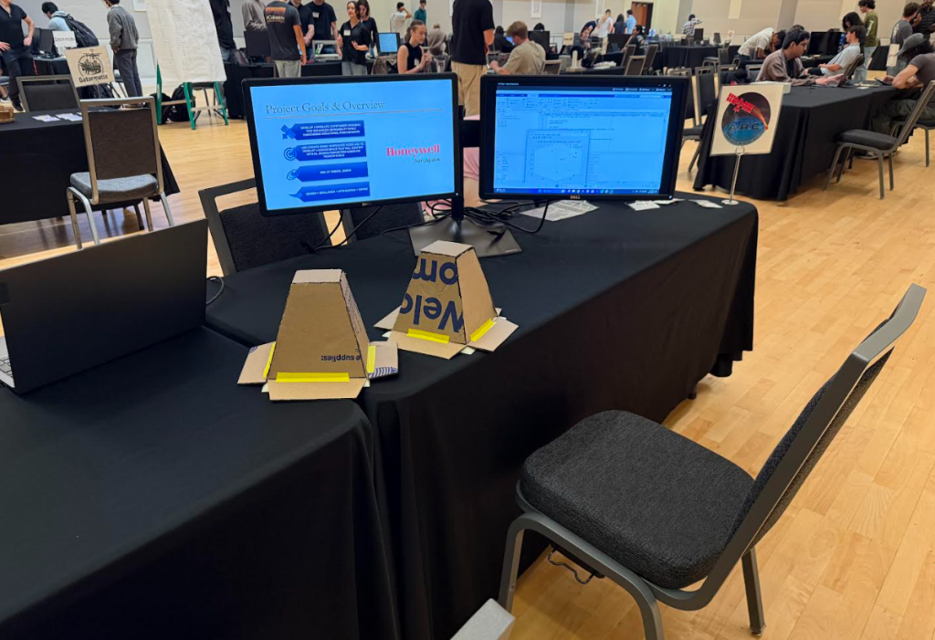
This week marked an exciting milestone for our IPPD team as we participated in Prototype Inspection Day (PID) at the University of Florida. During this event, we presented our project to a panel of IPPD alumni, technical professors, and academic professionals, sharing our progress and receiving valuable feedback to guide our next steps.
Our 20-minute presentation focused on outlining our project’s purpose, technical development, and future plans. We received two main categories of feedback: the first centered on presentation delivery, including our professionalism, clarity, and how effectively we communicated complex ideas. The second set of feedback involved technical insights, such as potential improvements to our design and simulation methods. Both types of feedback were incredibly helpful and will directly influence how we refine our project going forward.
In preparation for PID, our team put in extensive hours of effort, especially in running and finalizing our first Ansys Fluent simulation. This process took nearly 15 hours from setup to completion. Most of that time was spent learning the software’s various features, setting appropriate parameters, and understanding the computational fluid dynamics behind our system. Running this simulation marked a key step toward validating our design under re-entry conditions.
During our weekly meeting, we also discussed the assumptions and simplifications we will use in future simulation runs. Because our project involves complex re-entry dynamics, finding the right balance between realistic modeling and manageable scope has been a constant challenge. Our goal is to keep simulations as close as possible to real conditions while ensuring they remain achievable within our time and resource limits.
Overall, PID was both rewarding and challenging. Condensing months of research, design, and testing into a 20-minute presentation was no easy task, especially given how intricate our system is. Some audience members found it difficult to grasp all the technical details, which reminded us of the importance of clear communication and strong visuals when explaining complex engineering concepts.
As we move forward, we’re taking these lessons to heart. Our team plans to focus on improving how we present technical content, refining our simulation accuracy, and ensuring our design continues to evolve in line with both academic rigor and industry relevance. Prototype Inspection Day was a defining moment and a chance to see how far we’ve come as well as how much potential lies ahead.