This semester marked a major learning phase for our IPPD team as we began developing our re-entry “Design for Demise” solution for Honeywell Aerospace. Our primary objective was to build a strong foundation in ANSYS Fluent, understand the aerodynamic behavior of re-entry conditions, and prepare for the more advanced simulations we will run next term.
We spent much of the semester learning the fundamentals of ANSYS Fluent—how to create and refine meshes, assign boundary conditions, choose appropriate turbulence models, set up solvers, and interpret results. Because real re-entry conditions are extremely difficult to reproduce in the real world, having a reliable CFD workflow is essential to our project. Over time, we became more confident in our ability to set up simulations correctly, troubleshoot issues, and understand why the flow behaved the way it did.
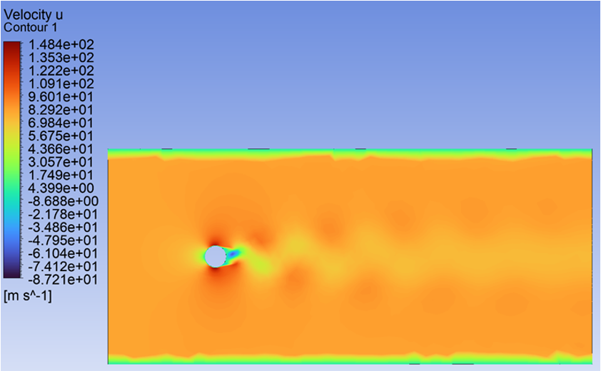
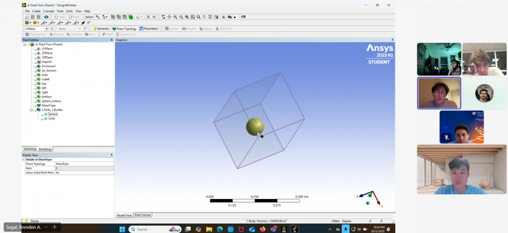
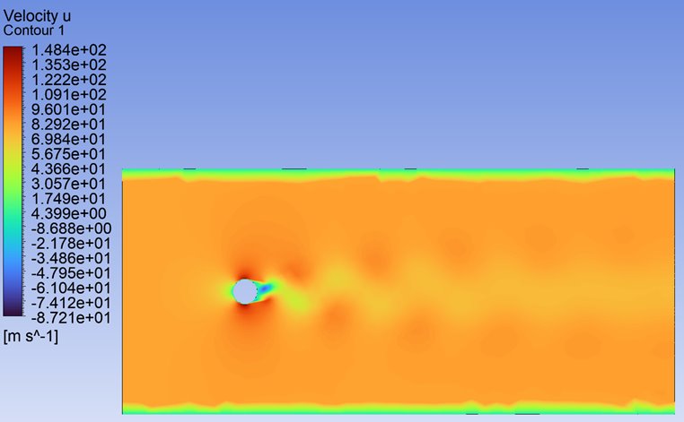
One of the most important milestones was completing a flow-over-a-cylinder proof-of-concept simulation. The cylinder is a classic test case in fluid dynamics, and running it allowed us to validate that our methods were correct. We observed the expected stagnation point on the front of the cylinder and identified alternating vortices known as a Von Kármán vortex street forming downstream. Understanding this phenomenon required us to revisit concepts from fluid mechanics and study how vortex shedding works and why it appears at certain flow regimes. This project strengthened not only our technical skills but also our ability to interpret and explain physical results.
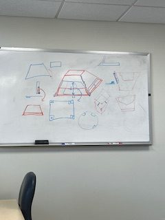
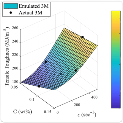
Another major achievement this semester was developing a Kriging surrogate model to optimize our design parameters before running full CFD simulations. Since high-fidelity simulations are computationally expensive, we needed a systematic way to determine which configurations were worth testing. To do this, we first identified the key geometric and physical variables of our design. We then used a structured set of sample points to train the Kriging model, which created a predictive map of how different parameter combinations influence performance. This model helped us narrow down the design space and select the most promising configurations for next semester’s simulations. Building the model taught us how surrogate modeling can guide engineering decisions and allowed us to work more efficiently with the resources we have.
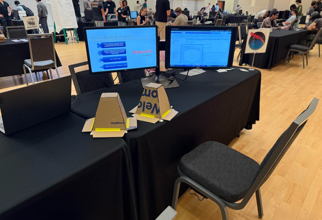
We also prepared and delivered our System Level Design Review. For the SLDR report, we wrote detailed sections explaining how ANSYS works, what simulations we ran, how the simulation process functions, and why this software is crucial for our mission. Presenting this information pushed us to think carefully about clarity and communication. Many of us realized the challenge of presenting technical information smoothly, and the experience gave us insight into how we can improve our presentation skills going forward.
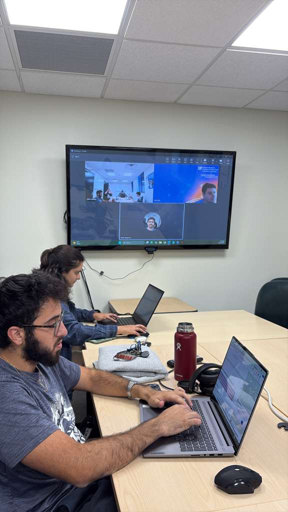
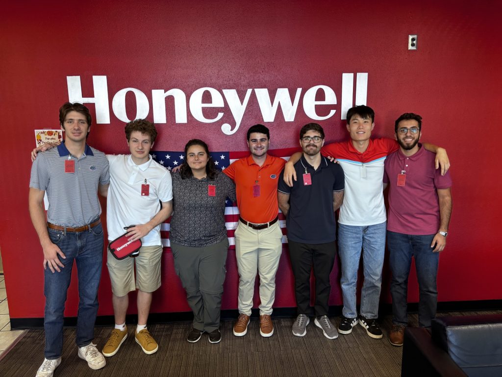
Throughout the semester, we grew significantly as a team. We learned how to divide tasks, explain complex ideas to one another, question results, and support each other as we worked through the learning curve of CFD, optimization, and re-entry physics. Even the challenges—such as understanding unexpected flow features or refining mesh strategies—played an important role in helping us become better engineers.
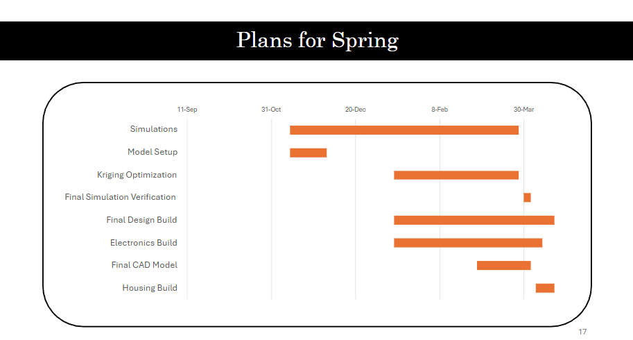
Next semester, our focus shifts toward simulations that are much more relevant to re-entry. We will begin modeling hypersonic flow conditions involving extreme Mach numbers, shock structures, and high thermal loads. Our simple test geometry will evolve into analyses of our actual design concepts, giving us insight into how they behave during re-entry and how we can improve their demisability. The Kriging model will continue to guide which configurations we test, allowing us to combine optimization and CFD to converge on a final design.
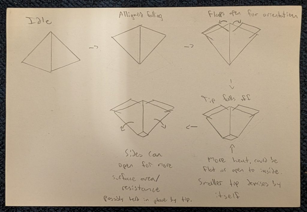
This semester laid the groundwork. We built the tools, established the workflow, validated our simulation process, and strengthened our ability to collaborate. Next semester, we take everything we’ve learned and apply it to the real engineering challenge of creating a design that safely and effectively breaks apart during re-entry. We’re proud of the progress we’ve made and excited for what’s ahead.