Hey folks!
We’re almost there with our Preliminary Design Review (PDR) and wanted to give you a quick, behind‑the‑scenes look at what we’ve been chewing on this week.
We’re talking P‑frust (a new way to say “pyramidal frustum”)
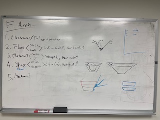
- Why the shape?
Think of a pyramid with a short top. That gives us surface area to play with while keeping the center of mass stable. Plus, it’s a good canvas for our “flaps” that pop out to suck up drag when the vehicle slams into the atmosphere.
- What’s in the flap‑drama?
We’re testing how long they are, how far they lean out from the body, and how that changes the center of pressure/gravity and heat generation
Visually
- 3‑D CAD (SolidWorks): We modeled dozens of “what‑if” variants, each a slightly tweaked frustum or flap combo.
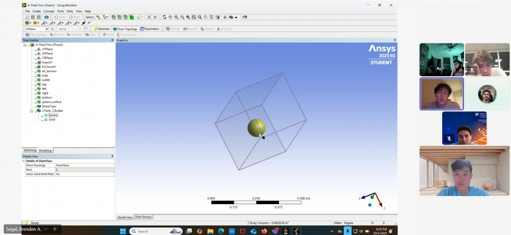
- Heat‑Up Analysis (ANSYS): Those CADs are pulled into a simulation engine that tells us where the air‑fire hits hardest and how fast the heat preforms. We down selected our variables to focus on
- Shape of the frustum (how vertex angle and weight distribution effects of COP, COM, and heat generation) 2.
- The design of the flaps (how flap length and angle from frustum effects of COP, COM, and heat generation)
- Later the material parameters will be defined and tested.
- Brant Chart: This simple, graphic roadmap will line up the work for the next few weeks to keep us organized
The Crew & Their Missions
| Who | Mission |
| Electrical Duo | Building the flap‑channeled wiring, control loops, and battery budget. +2 handle the tri‑state logic to keep the flap actuation smooth and ultra‑light. |
| Modeling Quintet | Each of us blocks out a new parametric “family.” We’ll push the parameters, run the heat‑flags, then hand off the best pairings to the electrical folks. |
We’re split to keep things moving. The electrical and modeling workflows are now tightly intertwined – a bit of code‑first, a bit of geometry‑first.
Road‑Map & Next Tweaks
- Lock the baseline shape in SolidWorks – we’re picking a prototype that balances drag and thermal load.
- Run the first ANSYS thermal snapshot – get a quick heat‑flux map so we know where the “hot spots” sit.
- Finalize the Brant Chart before the weekend – this ensures we joke about deadlines, not crisis.
- Material deep‑dive next week – high‑conductivity, low‑density alloys (think aluminum‑silicon and lightweight composites). We’ll compare them by melting point, oxidation dance, and weight.
At the end of the day, it’s a lot of math, a lot of questions to explore down the road. But we’re getting there – the P‑frust is almost ready to spring into action, and the flaps are ready to give the drag a performing‑arts twist.
Stay tuned for the next update – we’ll share the ANSYS plot that will either blow us away or make us rethink the whole angle.