Blog Posts

Week 5

This week was very build focused, with the team pushing forward on hardware progress and preparing for the next round of functional testing. We completed Build 2, which uses a larger diameter electrode, and continued refining the mechanical and electrical integration between the probe, PCB, and handle assembly. Alongside that, we finalized the design of our new two button PCB with fuse clips, which will help improve reliability and protection during testing

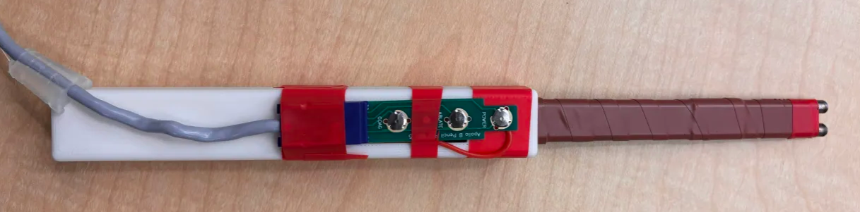
This is the PCB with the buttons and fuse clips to hold and have a stable connections to the electrode rods. Will order about 50 of them.

This is an alternative to connect to the rods for the mean time. Using thin copper tape then soldering wire onto it and soldering it the PCB.

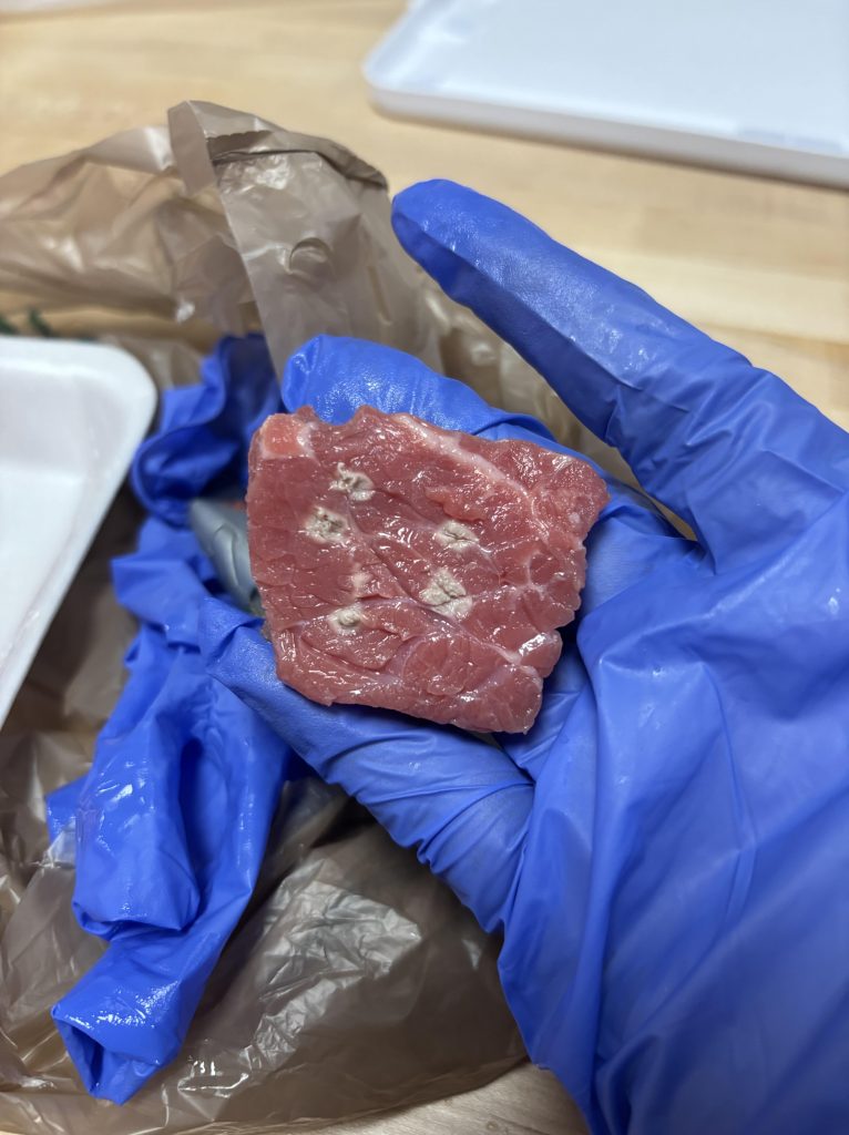
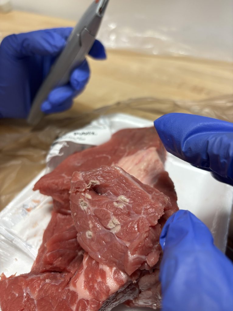
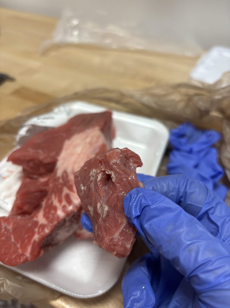
From a team workflow standpoint, we spent time coordinating lab schedules, wiring order, and assembly sequencing to keep builds moving efficiently. One risk we are monitoring is the delivery time of conductive silver epoxy, since that material is required to complete Build 3. If it is delayed, we will adjust assembly order but continue preparing for testing so we stay as close to schedule as possible. Next week, the main goals are finishing Build 3, beginning coagulation testing on steak for Builds 2 and 3, and printing the updated handle that includes the new PCB holder. We are also confirming scheduling details for the final sponsor presentation to make sure our timeline aligns with sponsor expectations.

Week 4

This week was very manufacturing and assembly focused as we pushed forward on our next prototype builds. The team worked on machining new electrode sets, including both a solid shaft version and a hollow shaft version. The hollow design will allow internal routing through the shaft while the solid design serves as a structural and electrical baseline. We coordinated machining, wiring order, and assembly timing so electrical work could be completed before final mechanical assembly.

Raw Electrode Comparison, Solid vs Hollow Design

These are two early stage electrode shafts. The left pair is the solid electrode design, while the right pair is the hollow electrode design that will allow internal routing through the shaft. At this stage, both are still in raw machined form and the distal tips still need to be shaped and smoothed to the final geometry. These parts will be finished on the lathe to achieve the final radius and surface finish required for consistent electrical performance and fluid interaction.

Moving forward, comparing these two designs will help us evaluate mechanical strength, manufacturability, and how each design supports our saline delivery strategy before locking in geometry for later prototype iterations.

Week 3

This week was composed of finishing up the composition of the electrical testing rig, capturing some electrical charactersitics of our prototype (similar data was found in comparision to Arthrex Documentation).

Oscilliscope capturing Coag 2 from AR9800 power console -> prototype electrodes across a 300Ω load

As expected, (one example, measurements were done for all modes under ablate 5), the measured Vrms closley match the AR9800s Limit/Test level documention! In the image shown above, MATH mode was used to subtract the two probe voltages across the resistor (as this is not a floating circuit, some extra percautions were taken as to not short anything or create any physical loops). We captured ~78Vrms, while Arthrex documentation, with a little math, expected 79.7Vrms, very close (1% difference)!

From this data we’ll record more charactersitics of the signal across 2 varying loads, with tissue loads following, replacing formulas for Irms with current probes (as tissue loads are varying loads, we can’t rely on constant equations).

Electrical fixture setup, disregard the long wires and loops (Electromagnetic Interference producers) as this was an informal experiement. Also, yes, that is a guitar shaped base.

Non-inductive load resistors were screwed to a wood base, with the same length of twisted wires connecting to a central perfboard with screw terminals, and solder ports for the probe to connect to.

We also order a few components essential to our prototyping process like heat shrink for the shaft, a new UV epoxy with UV light for faster prototyping, as well as copper foil to create a link between the pcb and electrode connections (stainless steel doesn’t solder well!).

Closing the week with a QRB (Qualification Review Board) presentation, we recieved vital feedback and comments on our progress for the project. The board belived our project was on track and overall presentation was great with some comments on formatting and font size.

Week 2 (Spring)

Welcome to Week 2 with ElectroFlow! This week was composed of active beef tissue coagulation experiments, a new method of attaching tubing (extermely quick, saved a substantial amount of time and money), and the start of the electronics fixture!

Illustration of nominal saline flow with new marine heatshrink tubing application. The two different diameter tubing are now correctly locked in place without the need to wait 72hrs for epoxy to cure!

New Marine Heat shrink! This specialized heatshrink cures in mear minutes, with adhesives preapplied to the inside, capable of holding our two different diameter tubing for quick and easy prototyping!

New electronic fixture testing! After confirming validity with our Coach, we will utilize EMI reducing methods (twisted wire pairs), current sensing resistors, math functions on oscilliscopes, and retrieve vital data on both non inductive load chassis resistors and tissue!

Week 1 (Working Saline Flow and Coagulation)

We are officially back for the spring semester, and the energy is high! After a much-needed break, the team is diving straight into the critical phase of our IPPD project for Arthrex.

Clearing the Blockages Our primary focus this week was tackling the mechanical challenges we identified last semester. We’ve ordered the final components needed to complete our testing rig, but the biggest win is in the assembly process.

Working Saline Flow!

Overhauling our epoxy application process to eliminate clogging and ensure perfect saline flow between the distal tips. With the design refined, we’ve ordered fresh beef samples to begin rigorous tissue testing. Our goal for the semester is clear: iterate, validate, and deliver a finalized, reliable probe to Arthrex.

Week 13 (Eureka, a working prototype!)

This week marked a huge milestone for our team. Just in time for the SLDR event, we assembled our first fully functioning prototype and finally got to see our design come to life. The PCB was mounted directly onto the 3D printed housing for easy access to wiring and components, which made troubleshooting and adjustments simple and fast.

We did hit one unexpected snag. An epoxy cure mishap left our saline delivery tube fully clogged, so no fluid could flow as intended. But that didn’t stop the test. A small dab of saline applied directly to steak tissue still produced visible coagulation with an estimated depth of 4-5 mm. Even without full functionality, the result was clear and encouraging.

The device is showing promising behavior, and now we move into an exciting next phase. Our goal is to collect performance data, refine the design, and run more controlled tests to shape the next iteration. The foundation is here, and the path forward is strong.

Tagged as:

Week 12

This week, the team continued working on the prototype build and made significant progress toward completing our first functional version. After finishing most of the machining and assembly, we were able to put together the first full prototype and immediately started evaluating it. We also took the feedback from our internal SLDR and began integrating those suggestions into both the physical design and the presentation we will give on the actual review day.

Most of the technical effort this week went into assembling the prototype. With the main components now machined, we focused on putting everything together and checking whether the design adjustments from last week translated well into the physical build. While doing this, we identified a few areas, mainly related to fit, alignment, and fluid delivery, that could need revisions before the final presentation.

At the same time, we continued updating our SLDR slide deck. This involved revising our system diagrams, cleaning up sections that changed after the internal review, and making sure the presentation clearly reflects the current state of the prototype. The goal was to keep the documentation fully aligned with what we have built so far.

Some of the key takeaways from this week were:

  • Successfully assembling the first full prototype and using it to evaluate system fit and overall configuration.
  • Applying the internal SLDR feedback to improve both the prototype and the clarity of our system explanation.
  • Planning on testing the initial prototype once fully assembled before the SLDR

Week 11 – Building our First Prototype

This week, our team shifted from planning to hands-on development as we began physically building our first functional prototype. After incorporating the feedback received during the Prototype Inspection Day, our focus centered on translating the refined design ideas into a physical prototype and preparing the documentation and presentation materials needed for the upcoming System Level Design Review (SLDR).

Most of our technical effort was directed toward prototype building. We began machining and assembling the primary components of the device, ensuring that the design adjustments suggested by coaches, particularly those related to fluid delivery and electrode positioning, were properly integrated.

We also dedicated significant time to developing our SLDR presentation. This involved organizing our current progress into a document, updating our diagrams, and reviewing the information from our PDR to update any decisions that we changed during the process.

Throughout the week, the team collaborated closely to maintain alignment between the build process and the system-level requirements. The main takeaways were:

  • Ensuring that our machining plan stays synchronized with the functional requirements established during PID.
  • Strengthening the clarity of our prototype for SLDR, particularly regarding fluid flow pathways and electrical integration.
  • Identifying potential bottlenecks in the assembly process so we can adjust the timeline before SLDR.

These insights helped guide our priorities going forward. Over the coming week, we will:

  • Continue machining and assembling the remaining prototype components.
  • Begin preliminary fit checks and dry assembly to ensure full system compatibility.
  • Finalize the SLDR presentation

Overall, this week marked an important transition from design refinement to physical implementation, setting the foundation for both a successful SLDR and a promising first prototype iteration.

Week 10 – Prototype Inspection Day (PID)

This week, our team participated in the Prototype Inspection Day. Since the PID serves as a checkpoint for evaluating progress and direction, our goal going into the event was to communicate where we currently stand in the development process and gather useful feedback to guide the next iteration of our prototype.

We presented two forms of prototypes:

  • A structural prototype created through 3D printing, which allowed us to demonstrate the geometry and expected assembly of our device.
  • A testing demonstration video using the Smith + Nephew Werewolf probe to show the method we will use to evaluate tissue effects once our own functional prototype is ready.

Through multiple presentation rounds and Q&A sessions, we received feedback from coaches across disciplines. The main takeaways were:

  • Clarify some design considerations related to how we should deliver fluid flow on our device.
  • Refine testing methods to ensure consistent measurement of tissue effect.
  • Update our timeline to reflect machining, assembly, and iterative testing more precisely.

This feedback provided clear direction for our next steps. Over the coming week, we will:

  • Finalize material procurement for machining.
  • Begin assembly planning for our first functional prototype iteration.
  • Develop structured testing protocols to evaluate tissue effect once the prototype becomes operational.

Week 9 – Preparing for the PID

This week, our team spent our time gathering data and a first stage structural prototype of our device for the upcoming Prototype Inspection Day on Tuesday, November 4th. In class, we were provided all the important details of this benchmark event, which are summarized below:

  • 15 minute presentation to a set of 2 judges + a 10 minute Q&A
  • Repeated presentations 3 times
  • Take notes in the presentations to keep track of feedback
  • Content
    • Define the goal of the prototype
    • Define the uses of the prototype
    • Define the type(s) of the prototype
    • Define the hypothesis associated with the prototype
    • Define the experimental plan with the prototype
    • Create and present a schedule for procurement, construction, and testing of the prototype and/or future prototype iterations

Our Plan

In discussing what we wanted to present in our PID presentation, we had to base the decision on what we had accomplished thus far. Since we had developed CAD drawings of our first iteration of the functional prototype (our deliverable to Arthrex), we decided that one prototype that we could present is a structural prototype of what we expect our first iteration to look like once we receive materials and complete the machining and assembly process. Therefore, we 3D printed these structural drawings to present at the PID.

To demonstrate functionality (provide a version of a functional prototype), we decided to use our designed testing methods for our future prototypes on the competitive market on the surgical device market, the Smith + Nephew Werewolf Probe. We did this for a few reasons. First, as discussed last week, we wanted to demonstrate that we could electrically map wire layout and PCB design of an RF Hemostasis probe to the AR9800, per the Arthrex scope of work. However, in order to go from there, we tested this device on meat to see the type of tissue effect that would be achieved with the design and materials used by the competitor. As we will discuss in our PID, the evaluation of future functional prototypes will be determined by metrics such as the depth of penetration of tissue effect and the area of spread on the surface of that effect. These will be measured with AR9800 power level as the independent variable and the time of coagulation as a constant.

More Photos from Functional Testing

Wish us luck this upcoming week at our PID!