Blog Posts

Week 6 – Other Process Simulators

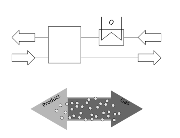
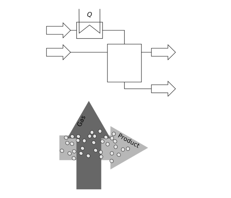
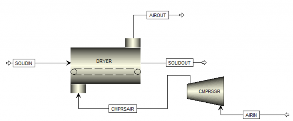
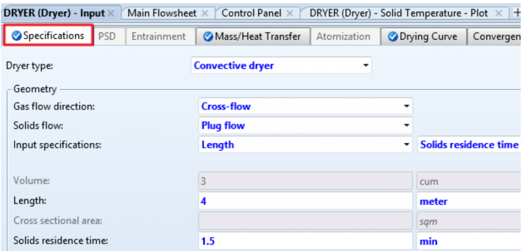
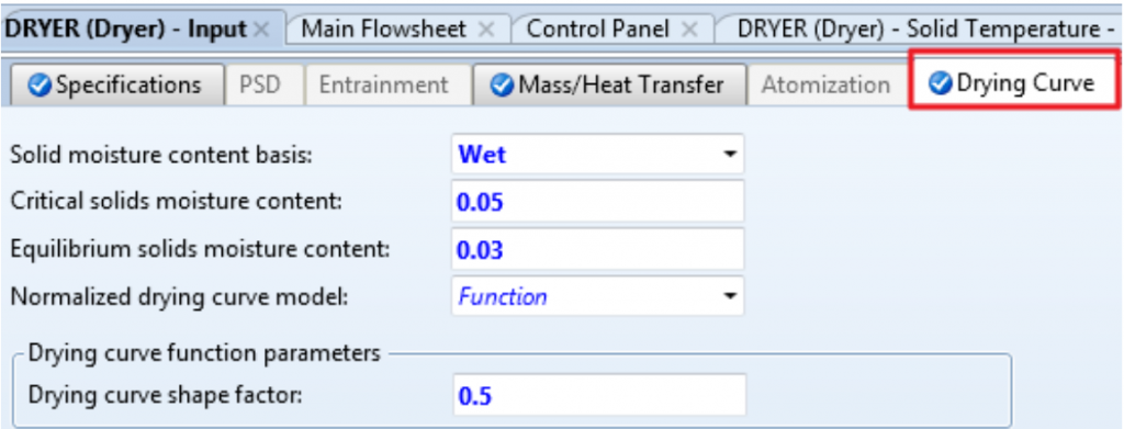
While we were investigating which process simulation software to use for our project, one of the options we were investigating was called SuperPro Designer by Intelligen [1]. This made it towards the top of the list because one of its listed features is that it has the capability to model a convective dryer. Below is an example of SuperPro Designer’s capability to simulate process equipment!

Image 1: An example photo from Intelligen’s website that has a process that is handling a material that would be similar to our feedstock [2] .

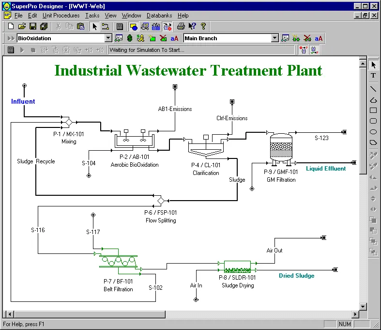
From the above example simulaton, we can tell that SuperPro has many similar features to Aspen Plus. Both simulators are capable of handling reaction thermodynamics, they are both capable of handling solids feed and product streams, they can both even handle convective drying! Ultimately, we ended up choosing to use Aspen Plus because all members of our ChemE team have the ability to access it, while we only have very limited access to SuperPro Designer.

Relationships:

[1] Intelligen, Inc., “SuperPro Designer Product Features,” Intelligen, SuperPro Designer, SchedulePro, EnviroPro, https://www.intelligen.com/products/superpro-product-features/ (accessed Feb. 20, 2025).

[2] Intelligen, Inc., “Wastewater Treatment and Pollution Control,” Intelligen, SuperPro Designer, SchedulePro, EnviroPro, https://www.intelligen.com/industries/wastewater-treatment/ (accessed Feb. 21, 2025).

Week 5 – CFD Model Improvements

Our MechE Team has been diligently working on our Ansys Fluent simulation and all its required subcomponents. One piece of this that they wanted to show off was the CAD model of the ductwork that they have been working on. This is an image of the Solidworks model being used in Ansys fluent showing some of the boundary conditions.

Image 1: Screenshot from Ansys fluent showing inlet and outlet boundary conditions.

This is one part of the major system that will be modeled in Ansys fluent by our MechE team. This piece of ductwork serves to show that the best way we have figured out how to simulate airflow is by using the volume of fluid inside the ductwork as the volume of air that needs to flow.

Week 4 – Site Visit Complete!

Last week, Dry Guys conducted a site visit to GreenTechnologies facility to run an experiment on the dryer for data collection! With the help of the operations team at GreenTechnologies, we were able to successfully collect the data we came looking for. The data collected will help us both construct our simulations and make them more accurate, which will enhance our recommendations to GreenTechnologies for optimizing their dryer. Below is an image of a couple of our team members actively collecting data from the site visit!

Image 1. Two members of Dry Guys using our anemometer to measure air speed and temperature of the dryer exhaust.

Week 3 – Aspen Assumptions

When using Aspen Plus to model any piece of equipment, there are certain assumptions that the software automatically makes to ensure that it will have the ability to converge to a solution.
For modeling a Convective Dryer, the assumptions that are made are as follows:
– The Dryer is adiabatic (no heat losses).
– The Dryer gas and its particles pass the dryer in plug flow.
– The particles are ideally mixed in the lateral direction.
– The moisture content and temperature are spatially constant in every particle.
– Intraparticle drying resistances are taken into account by applying the concept of normalized, single-particle drying curve of van Meel.

The other assumption that we are making is that the air is in a counter current and cross-flow configuration. Figure 1 depicts what counter current flow looks like in practice. Counter current flow is used to put the hottest air to the driest part of the product. Figure 2 depicts cross-flow in practice, and it is used because it provides the most efficient heating of the material. Combining the two diagrams would give you the air flow path that we are trying to model.

Figure 1. Counter Current diagrams [1].
Figure 2. Cross-flow diagrams [1].

References:
[1] Aspen Plus V11 Help Menu. AspenTech, 2019.

Week 2 – Requirements for Drying in Aspen

As we dive deeper into simulating GreenTechnologies equipment, our ChemE team would like to share some more Aspen Plus information!

When setting up a unit operation in Aspen Plus seen in figure 1, you have to not only specify what streams are and where they are going, but also what is going on inside the unit, which can be seen in figure 2. In figure 2, some of the major options that we have to define are the dryer type, the gas flow, and the solids flow. For the dryer type, there are 2 options to choose from – shortcut or convective. They use the same type of model behavior, however the convective dryer is a much more rigourous model which requires more specified parameters from the user. We have chosen to go the path of the convective dryer to get a model that is closer to our experimental data. The flows are both choices that were made when the equiment was installed, and we have obtained GreenTechnologies’ equipment set up and input it into our model.

Figure 1. An Example dryer with inputs and outputs [1].
Figure 2. An example Dryer specifications tab where the user defines the type and flow pattern of the dryer [1].

There is one more major tab that is important to getting a functional simulation. This is the Drying Curve tab under the dryer properties, which can be seen in figure 3. This tab specifies the target and equilibrium moisture contents, which are critical to recieving a working dryer. This tab also specifies the drying curve function and shape, which is something our Feedstock team will be determining in the lab soon.

Figure 3. An example drying curve tab for the dryer properties [1].

References:

[1] K. I. M. Al-Malah, Aspen Plus: Chemical Engineering Applications. Hoboken, NJ: Wiley, 2022.

Week 1 – Welcome Back!

We would like to welcome everyone back from a lovely winter break! The Dry Guys are excited to hit the ground running and continue to work on our project.

Image 1: A welcome back banner [1].

We made a quick site visit to get some necessary dimensions of the dryer itself for modeling it in both Ansys CFD and Aspen Plus. With these dimensions we are confident that we can have working models soon and accurate models to follow!

References:
[1] cstock56, “Welcome back sticker – welcome back – discover & share gifs,” Tenor, https://tenor.com/view/welcome-back-gif-19477654 (accessed Jan. 16, 2025).

Week 15 – SLDR Conclusions and Semester End!

We have come so far and we can’t believe that the semester is already over! We worked diligently to prepare for our SLDR presentation with our sponsor GreenTechnologies, and it paid off. Our sponsor was very impressed with the progress we have made on our project and they are just as excited as we are to tackle all the challenges that will come in next semester.

We look forward to overcoming what the spring semester will bring us, but we are ready for a short break. The Dry Guys will be off from school over the winter break and will return on January 13th, 2025. We will be actively thinking about all our next steps while we are away, see you soon!

Image 1: Dry Guys at the end of practicing for the SLDR presentation, feeling happy and ready to present to our sponsor.

Tagged as:

Week 14 – Thanksgiving Break

This week, the team took a step back from the work and spent some time with family for thanksgiving. We hope everyone takes step back to enjoy some time with their family this week – have a happy thanksgiving!

Image 1: A depiction of a fall harvest with the words “happy thanksgiving” [1].

References:
[1] Buffalo Tungsten, “Happy Thanksgiving,” Buffalo Tungsten, https://buffalotungsten.com/happy-thanksgiving/ (accessed Nov. 25, 2024).

Week 13 – Peer Review SLDR Takeaways

As SLDR approaches, we were given the opportunity to participate in peer reviews with some of the other teams to get feedback and potential improvements before we present to our sponsor.

Image 1: A screenshot of our title slide for SLDR.

One of our biggest pieces of criticism was on a technical component that many people just didn’t understand. Being able to get this feedback allows us to have the time to make this more understandable and better thought out, which is super helpful! The majority of the responses had very good tips about formatting and clarity within the slides which we plan to implement over the next week.

Week 12 – PID Takeaways

A fantastic success! All of our judges rated us really well for our prototype at this event and left us with some very good feedback.

A common comment from the judges was to better explain what all our simulations are doing and why they are important to the completion of our project.

Another really good piece of feedback we received was to discuss the hand-off of our project details to our sponsor. It is really important that they can actually use the files and information that we give to them so that this project has actual value to them outside of just a recommendation.

Image 1: A picture of our team explaining our prototype to 2 judges. Photo courtesy of Qingyu Yang.