Our CFD is excited to share some important findings that they discovered while simulating various test cases of the dryer. Without sharing anything too specific, we will discuss a series of different images from 3 different test cases here. Image 1 below will be the first test case with low recirculation flow and regular mass flow inside the dryer.
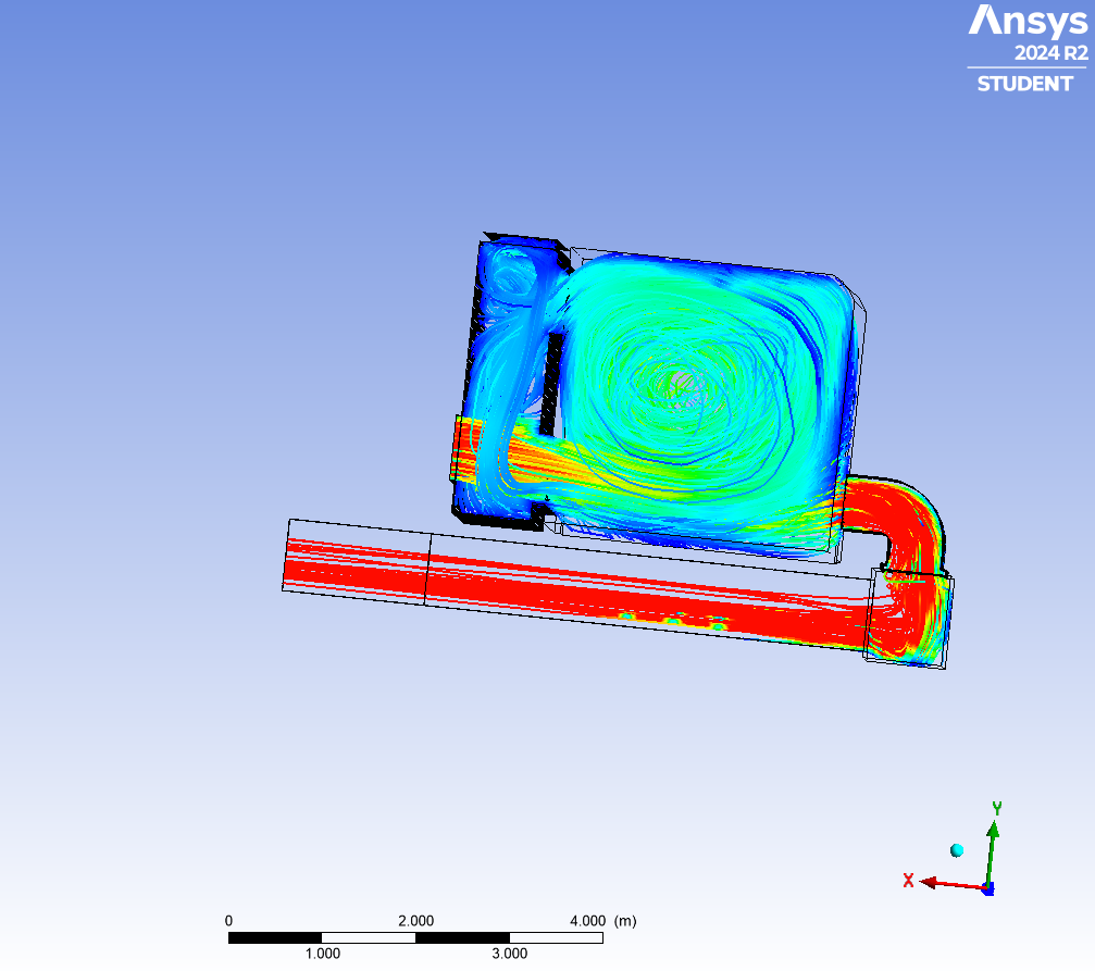
From Image 1, we can see that the lines – which represent airflow paths – are fairly well distributed inside the dryer. This means that the dryer has an even distribution of air inside that is making contact with the feedstock. Next, we will investigate design recirculation and normal mass flow in Image 2.
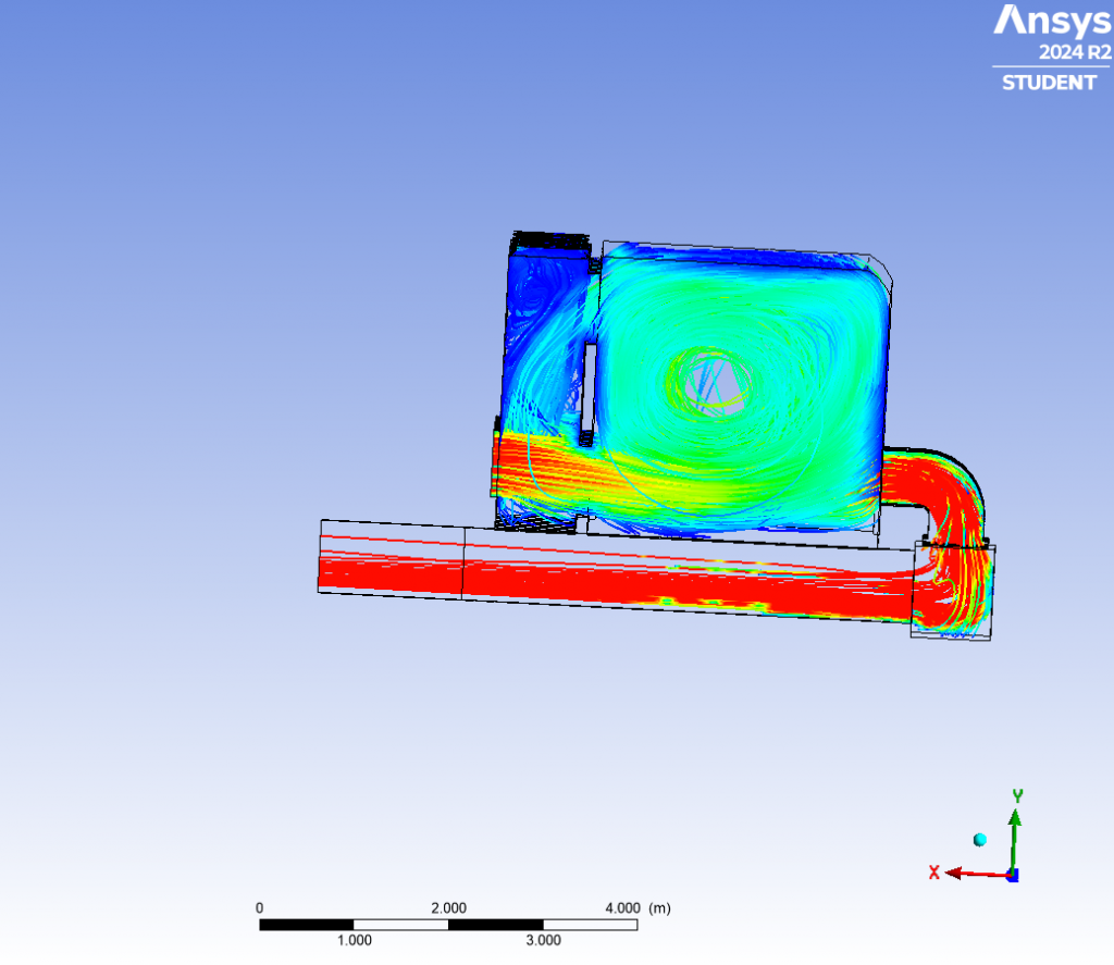
From this test case, we can see that a hole has appeared in the middle of the dryer where no air flow paths reach. This is significant because we can now draw the conclusion that increasing the speed of the recirculation fans pulls air away from the middle of the dryer. Finally, we will investigate one last test case with high recirculation and normal mass flow in Image 3.
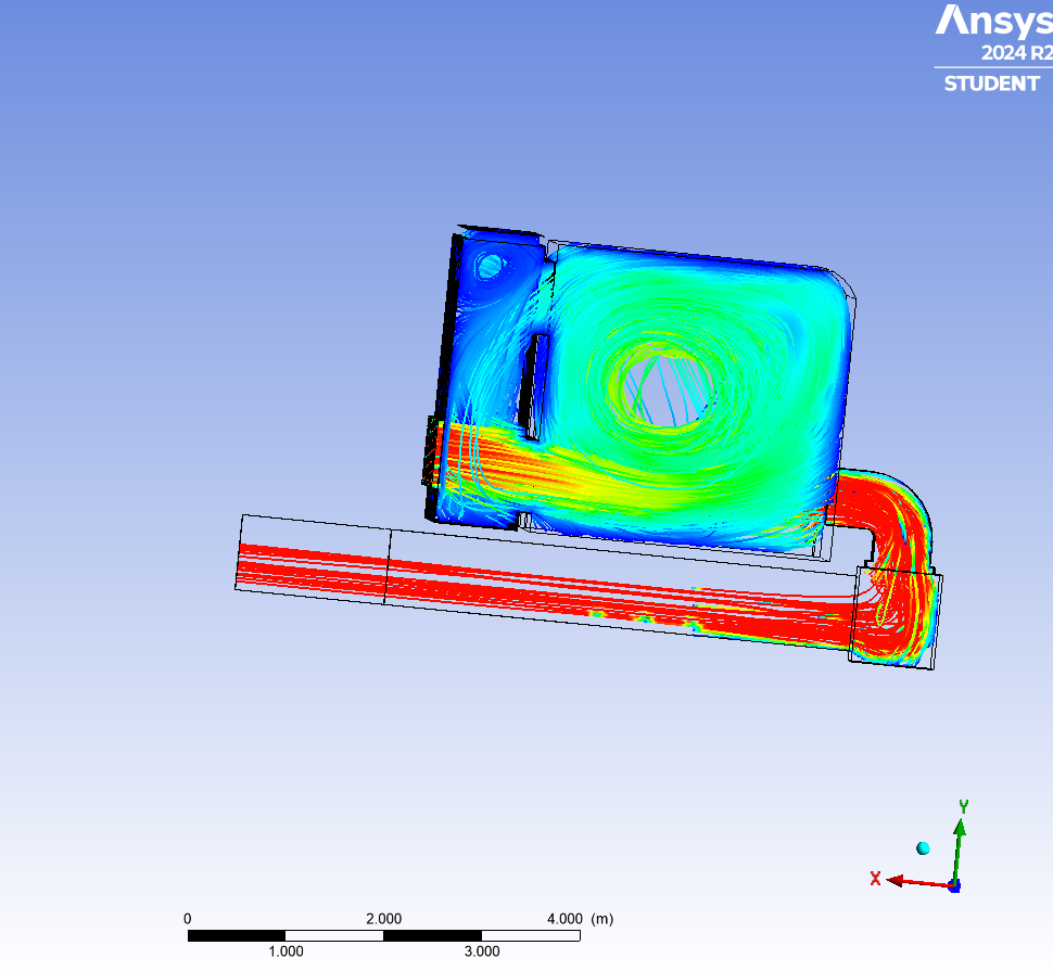
In this test case, we can now see that the hole in the center of the dryer has become more exaggerated and at this point it is likely impacting the mass and energy transfer between the air and the feedstock because it is reducing the overall surface contact between the two materials. This is significant because this impacts the overall performance of the dryer and the quality of the final product. We can now confidently say that increasing recirculation pulls air away from the center of the dryer and impacts the performance of the dryer. We also believe that the overall mass flow rate of air is important and may also impact the performance of the dryer, so will be testing that in the weeks to come!