The team is continuing to make improvements to the overall system. The sensor testing has continued with improved readings made possible by the electrical team. More 3D printing updates are on the way as well as the mechanical team has been improving the housing and working on flexible tube attachments.
Sensor Reading Testing
The electrical team has improved the Hall pulse sensor reading through the use of an ESP32, which is used as a dedicated microcontroller. Through incorporating ESP32, a new sensor reading system was devised to address inaccuracies in sensor reading.The electrical team has hypothesized that the primary reason for the inaccuracy from the sensor testing last week is the latency introduced by a non-real-time OS. Since the Raspberry Pi runs a traditional OS, its hardware communication relies on scheduled task execution, which may result in missed pulse readings and, consequently, lower measured flow rate.As illustrated in the diagram below, the OS schedules multiple tasks, including sensor input checks. However, because task execution follows a predefined queue rather than a real-time interrupt system, there can be a significant delay between the initial sensor state check and the actual pulse detection. This delay affects pulse counting, time elapsed measurement, and subsequent flow rate computation.
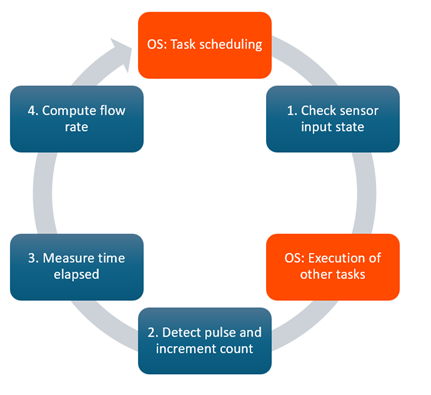
a traditional operating system (RPi with Linux)
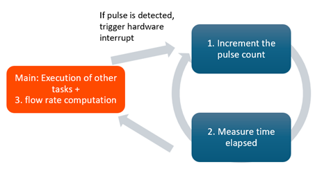
In contrast, the ESP32 offers real-time capabilities with its dedicated hardware timers and interrupt-driven processing. It can handle high-frequency pulses more reliably by triggering hardware interrupts whenever a pulse is detected, regardless of the execution state of other tasks. As shown in the diagram below, the ESP32 immediately interrupts ongoing tasks to process the sensor reading, incrementing the pulse count and measuring elapsed time with minimal latency.
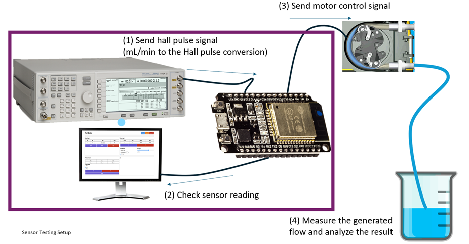
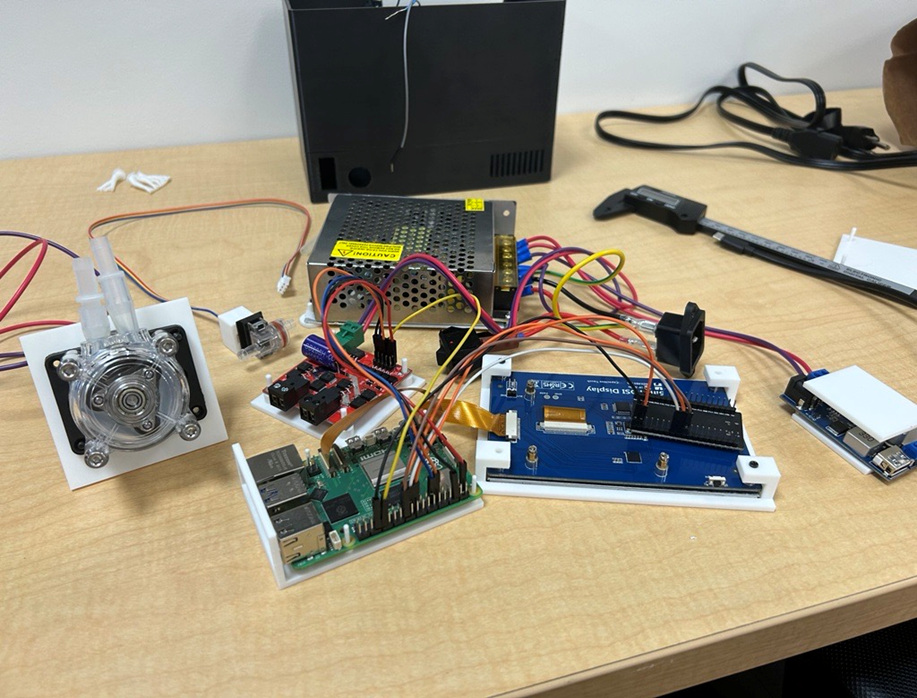
The testing for the new sensor reading system was conducted using the same method and setup as before, except the Raspberry Pi is replaced with the ESP32, as shown below.
Housing Update
The mechanical team has been sizing all the components that will be fixed within the housing. The different sizing is to ensure that all the screw holes placed within the CAD model will match to the intended components. An updated model will be printed in the next week that will include access to USB ports for connection to a keyboard and mouse.
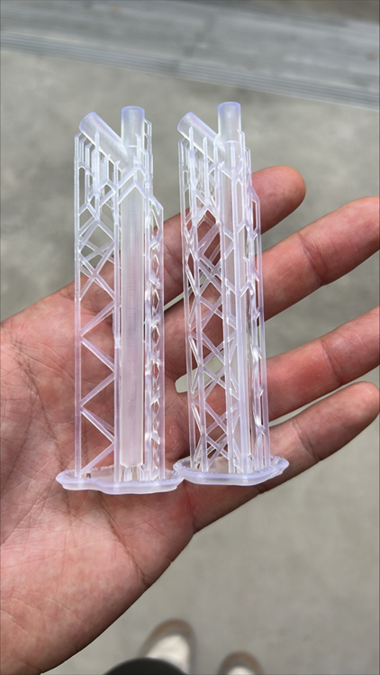
Tube attachment prints
The tube attachments are now being printed using resin printers within the chemical engineering department! The resin printers will give the models a smoother finish and allow the lumen to be a much smaller size than the FDM printing allowed the team. To test how much the prints shrink after they finish printing, the team printed 2 test tube attachments with the clear, hard resin available. The team will measure the difference in size and adjust the design for future print iterations.