More and more parts are being added to the system! The mechanical team has been hard at work at CAD and researching parts to buy to bring our project to the next level. The electrical team has also been very busy this week with testing flow generation and the sensor readings.
Housing Update
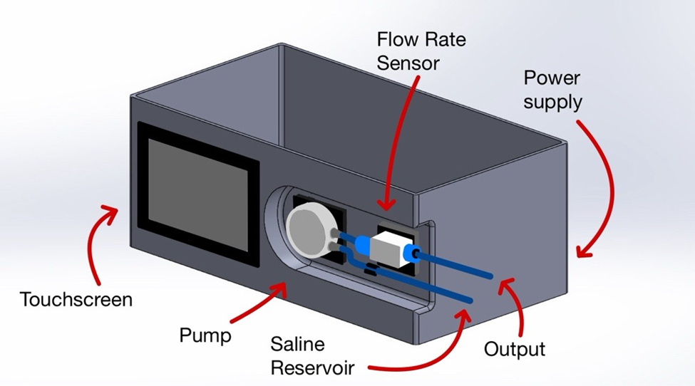
To start off with, the housing for the pump electrical components has been upgraded to add more spacing as well as improve the overall aesthetic of the system. The housing has increased in length to allow the pump and flow rate sensor to be lined up horizontally to the touch screen, and indentations have been made to prevent any components from sticking outside of the walls.
The Remote Control
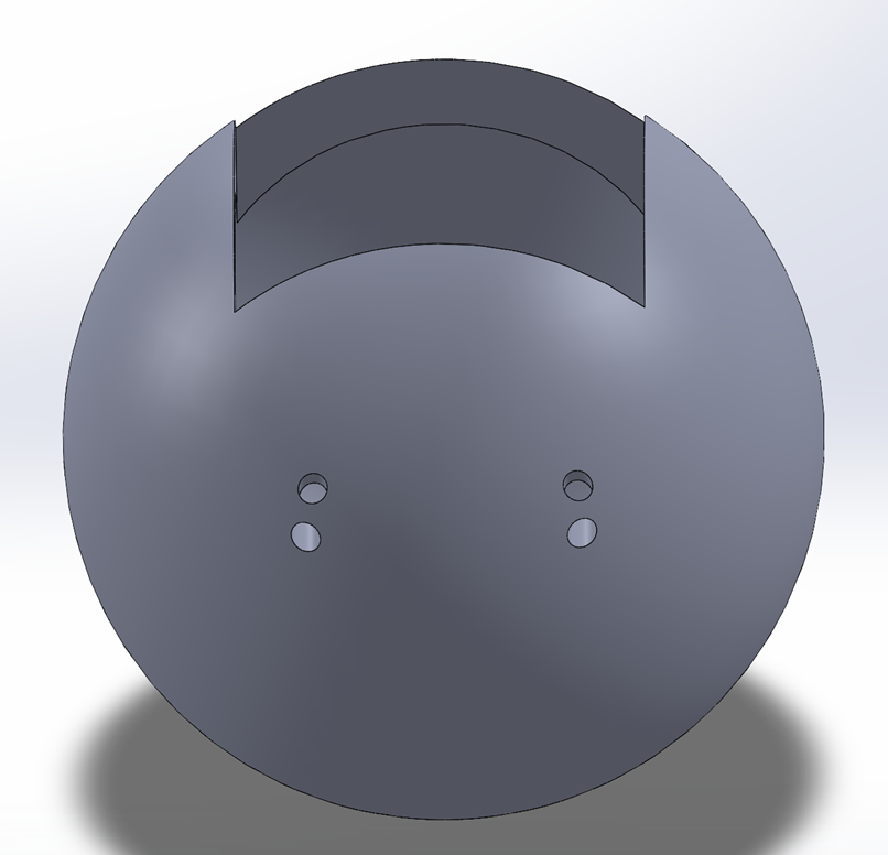
The team has been researching ways to integrate a remote control to the system. This remote control will allow the user to hold the tube attachment and control the flowrate of the fluid leaving the system at the same time. The ability to aim the jet of fluid and the flow rate of the stream of fluid will help the user to have more control of the system whilst in use.
A Testing Site
To get everyone as excited about our project as we are at FDR, we have modeled a testing site for observers to try out our system! This model will help display the control of fluid flow the system gives users by providing a target for them to aim the stream of fluid at. It will also help to contain the fluid that leaves the system during FDR.
Testing Flow Generation
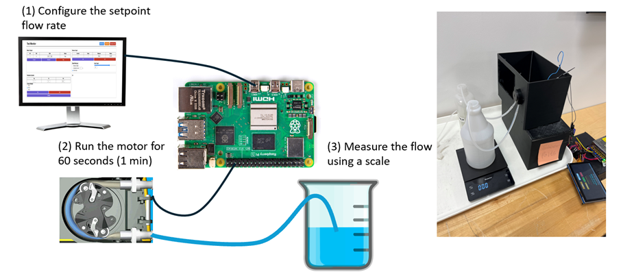
The electrical team tested the flow generation of the overall system by configuring the flow rate on the system and measuring the flow using a scale after 60 seconds have past. The testing results showed flow generation ranges from 0 mL/min to 73.1 mL/min, never exceeding past 75 mL/min. Refilling of water in the supply bottle may have introduced noise, but the trend remains consistent. The most accurate flowrate was when the setpoint was around 60-65 mL/min. The overall success rate was 13.6%. This low success rate indicates that the team requires a peristaltic pump that can provide a higher torque to achieve the desired flow rate range. An EMI filter would also be necessary to reduce electrical noise and improve the flow rate accuracy.
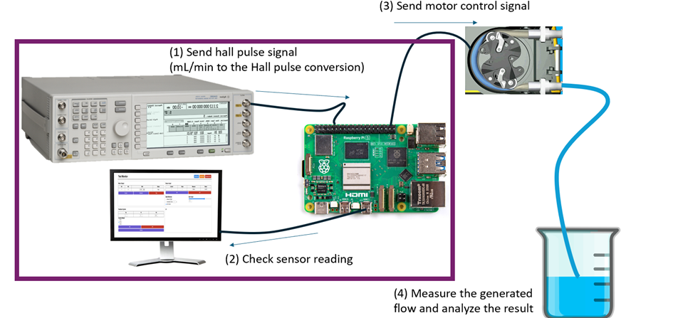
Sensor Testing
The electrical team have also tested the sensor readings by sending a hall pulse signal to the Raspberry Pi, checking the sensor readings displayed on the testing monitor, and measuring the generated flow. From this testing, the sensor readings were significantly lower than the actual signal transmitted. This could be due to inefficient software algorithms and hardware deficiencies. To address this, the software will be updated first. However, if this does not resolve the issue, the team will consider new hardware components such as an ESP 32 to offload processing from the Raspberry Pi, and provide fast and reliable data transfer to support the PID loop.