Happy Pi Day (March 14th gives the wonderful date of 3.14)! The team has pushed forward with so many more improvements and testing for the system that we deserve some pie…
A New GUI
The electrical team has been developing the next GUI for the system. This new GUI component will replace the old LCD screen with a Nextion Enhanced 3.5” LED touchscreen.
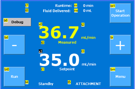
This GUI component will communicate with the ESP32 to send the input given by the user. The user will be able to select an attachment mode which will adjust the pump to the parameters necessary for the flow rate displayed on the screen and produced by the pump to be in sync with one another. The main page of the GUI will include the run/stop and increase/decrease setpoint flow rate buttons. It will also include the read time sensor reading update alone with the metrics counted. Another feature that has been added to the GUI is a keyboard that is displayed on the screen when the user wants to change the flow rate to a specific number.
| Var | Type | Description/Action |
| tm0 | timer | Track runtime & fluid delivered every 1s |
| ID | Type | Description/Action | Text/Value/etc. |
| bt0 | Dual-state button | 0: Switch to run state 1: Switch to stop state | 0: “Run” (stop state) 1: “Stop” (run state) |
| bt1 | Dual-state button | Start/stop runtime & fluid delivered measurement | 0: “Start Operation” (inactive mode) 1: “Stop Operation” (active mode) |
| bd | button | Decrease the setpoint step to be decided | “-“; large font |
| bi | button | Increase the setpoint step to be decided | “+”; large font |
| bm | button | Transition to Page Start | “Menu” |
| nr | number | Runtime measured | “[n] min”, [n]: runtime |
| ns | number | Fluid delivered measured | “[n] mL”, [n]: Fluid delivered |
| x0 | float | Current sensor reading | XX.X or 100. |
| x1 | float | Setpoint flow rate When selected, prompt key | XX.X or 100. |
| t4 | text | Current state display | “[s]”, [s]: corresponds to current state |
| t5 | text | Selected tool display | “[s]”,[s]: tool |
Sensor Troubleshooting and Improved Reading
The electrical team has also worked to troubleshoot the flowrate sensor to produce clear digital waves. Beforehand, the direct measuring of the sensor resulted in analog waves and no signals were produced due to flow. Yiwei was able to have a meeting with Silver Instruments, the manufacturer of the product, through a phone meeting to discuss issues with the flowrate sensor. After this meeting, the team was able to have the sensor produce clear digital waves through the use of a resistor ladder to manually adjust the voltage level to 3.3V for the ESP32’s specifications. The sensor is now able to read precise pulse counts at 200 millisecond sampling frequency.
Heat Generation Testing
The mechanical team has conducted heat generation testing to see how effective the system is at cooling a target area during a drilling operation. The team tested the flow rates 0 ml/min, 15mL/min, 50 mL/min, and 80 mL/min over a course of 30 seconds. Temperature of the surface was taken every 10 seconds in degrees Celsius to keep track of any temperature changes throughout the test trials. It was determined that our system did a good job at keeping the heat of the surface from increasing too much during the drilling operation.
More 3D Printing!
Two more 3D prints are in the process of being made! The first 3D model is the holder for the remote control that will control the flow rate for the system. This remote is designed such that it can be attached to the tube attachments allowing the user to aim and control flow rate in the same hand. The control will specifically be able to turn on/off the flow of fluid as well as increase/decrease the flowrate. The second 3D model is representative of a testing space, where the team will be able to use different materials such as foam to serve as an interior. The team will use this model as a way to test the functionality of our attachments and system while in a more confined space. Multiple insertion holes were added to allow for different angles, and a point of drainage was added as well.